MSTP Multi-process
Background
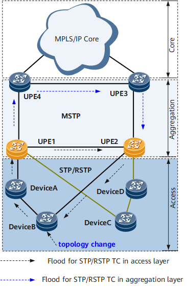
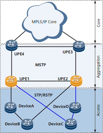
On the network shown in Figure 1:
UPEs are deployed at the aggregation layer, running MSTP.
UPE1 and UPE2 are connected by a Layer 2 link.
Multiple rings are connected to UPE1 and UPE2 through different ports.
The devices on the rings reside at the access layer, running STP or RSTP. In addition, UPE1 and UPE2 work for different carriers, and therefore they need to reside on different spanning trees whose topology changes do not affect each other.
On the network shown in Figure 1, devices and UPEs construct multiple Layer 2 rings. STP must be enabled on these rings to prevent loops. UPE1 and UPE2 are connected to multiple access rings that are independent of each other. The spanning tree protocol cannot calculate a single spanning tree for all devices. Instead, the spanning tree protocol must be enabled on each ring to calculate a separate spanning tree.
MSTP supports MSTIs, but these MSTIs must belong to one MST region and devices in the region must have the same configurations. If the devices belong to different regions, MSTP calculates the spanning tree based on only one instance. Assume that devices on the network belong to different regions, and only one spanning tree is calculated in one instance. In this case, the status change of any device on the network affects the stability of the entire network. On the network shown in Figure 1, the devices connected to UPEs support only STP or RSTP but not MSTP. When MSTP-enabled UPEs receive RST BPDUs from the devices, the UPEs consider that they and devices belong to different regions. As a result, only one spanning tree is calculated for the rings composed of UPEs and devices, and the rings affect each other.
To prevent this problem, MSTP multi-process is introduced. MSTP multi-process is an enhancement to MSTP. The MSTP multi-process mechanism allows ports on devices to be bound to different processes. MSTP calculation is performed based on processes. In this manner, only ports that are bound to a process participate in the MSTP calculation for this process. With the MSTP multi-process mechanism, spanning trees of different processes are calculated independently and do not affect each other. The network shown in Figure 1 can be divided into multiple MSTP processes by using MSTP multi-process. Each process takes charge of a ring composed of devices. The MSTP processes have the same functions and support MSTIs. The MSTP calculation for one process does not affect the MSTP calculation for another process.

MSTP multi-process is applicable to MSTP as well as RSTP and STP.
Purpose
Greatly improves applicability of STP to different networking conditions.
To help a network running different spanning tree protocols run properly, you can bind the devices running different spanning tree protocols to different processes. In this manner, every process calculates a separate spanning tree.
Improves the networking reliability. For a network composed of many Layer 2 access devices, using MSTP multi-process reduces the adverse effect of a single node failure on the entire network.
The topology is calculated for each process. If a device fails, only the topology corresponding to the process to which the device belongs changes.
Reduces the network administrator workload during network expansion, facilitating operation and maintenance.
To expand a network, you only need to configure new processes, connect the processes to the existing network, and keep the existing MSTP processes unchanged. If device expansion is performed in a process, only this process needs to be modified.
Implements separate Layer 2 port management
An MSTP process manages parts of ports on a device. Layer 2 ports on a device are separately managed by multiple MSTP processes.
Principles
Public link status
As shown in Figure 1, the public link between UPE1 and UPE2 is a Layer 2 link running MSTP. The public link between UPE1 and UPE2 is different from the links connecting devices to UPEs. The ports on the public link need to participate in the calculation for multiple access rings and MSTP processes. Therefore, the UPEs must identify the process from which MST BPDUs are sent.
In addition, a port on the public link participates in the calculation for multiple MSTP processes, and obtains different status. As a result, the port cannot determine its status.
To prevent this situation, a port on a public link always adopts its status in MSTP process 0 when participating in the calculation for multiple MSTP processes.
After a devices normally starts, MSTP process 0 exists by default, and MSTP configurations in the system view and interface view belong to this process.
Reliability
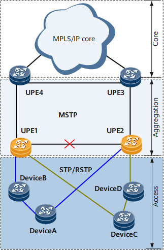
On the network shown in Figure 2, after the topology of a ring changes, the MSTP multi-process mechanism helps UPEs flood a TC packet to all devices on the ring and prevent the TC packet from being flooded to devices on the other ring. UPE1 and UPE2 update MAC and ARP entries on the ports corresponding to the changed spanning tree.
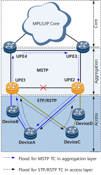
On the network shown in Figure 3, if the public link between UPE1 and UPE2 fails, multiple devices that are connected to the UPEs will unblock their blocked ports.
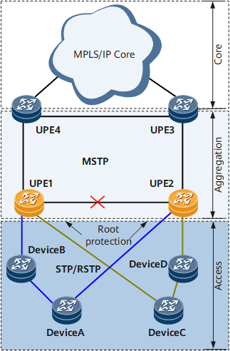
Assume that UPE1 is configured with the highest priority, UPE2 with the second highest priority, and devices with default or lower priorities. After the link between UPE1 and UPE2 fails, the blocked ports (replacing the root ports) on devices no longer receive packets with higher priorities and re-performs state machine calculation. If the calculation changes the blocked ports to designated ports, a permanent loop occurs, as shown in Figure 4.
Solutions
To prevent a loop between access rings, use either of the following solutions:
Configure root protection between UPE1 and UPE2.
If all physical links between UPE1 and UPE2 fail, configuring an inter-board Eth-Trunk link cannot prevent the loop. Root protection can be configured to prevent the loop shown in Figure 4.
Use the blue ring shown in Figure 5 as an example. UPE1 is configured with the highest priority, UPE2 with the second highest priority, and devices on the blue ring with default or lower priorities. In addition, root protection is enabled on UPE2.
Assume that a port on S1 is blocked. When the public link between UPE1 and UPE2 fails, the blocked port on S1 begins to calculate the state machine because it no longer receives BPDUs of higher priorities. After the calculation, the blocked port becomes the designated port and performs P/A negotiation with the downstream device.
After S1, which is directly connected to UPE2, sends BPDUs of higher priorities to the UPE2 port enabled with root protection, the port is blocked. From then on, the port remains blocked because it continues receiving BPDUs of higher priorities. In this manner, no loop will occur.