Y.1564 Ethernet Service Activation Test
Background
Carriers hope to learn the performance and running status of existing deployed networks before rolling out services. Information obtained helps make business proposals and promote services. Obtaining reliable performance data requires a highly reliable and accurate performance test method.
IETF released a standard protocol in 1999. In compliance with this protocol, Huawei developed a generalflow test methodology for measuring network performance. Although acceptable and valid, the generalflow test has the following drawbacks:
- Test results reflect performance quality, but do not verify whether services meet guaranteed performance settings specified in service level agreements (SLAs).
- No methods are provided to verify network configuration or test indexes, such as the committed information rate (CIR), excess information rate (EIR), or color mode (CM).
ITU-T released Y.1564 "Ethernet Service Activation Test Methodology" in 2011, which provided a new test method called an Ethernet service activation test. Compared with a generalflow test, an Ethernet service activation test provides more functions, supports multi-service scenarios, and outputs more accurate and reliable results, which allows carriers to better understand the performance of their networks before leasing them to customers.
Related Concepts
Bandwidth profile
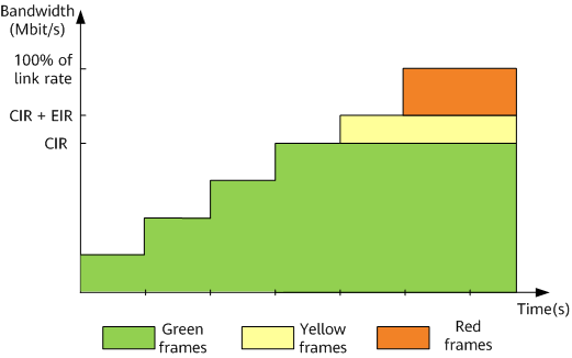
A bandwidth profile defines the bandwidth that a carrier assigns user services to enter a carrier network and the priorities based on which the user services are processed.
The bandwidth profile defines the CIR and EIR to limit service traffic.
Service frames are marked a specific color based on the CIR and EIR:
- Traffic is marked green if its bandwidth is lower than or equal to the specified CIR.
- Traffic is marked yellow if its bandwidth is higher than the specified CIR but lower than or equal to the sum of the specified CIR and EIR.
- Traffic is marked red if its bandwidth is higher than the sum of the specified CIR and EIR but lower than or equal to the link rate.
In addition to the CIR and EIR, the color mode (CM) is used to select a traffic measurement algorithm. The color mode allows user devices to set priority fields, such as 802.1p or DSCP, in service traffic before carrier network devices measure traffic based on the CIR and EIR and process the traffic.
Either of the following color modes can be used:
- Color-aware mode: Before entering a carrier network, higher priority traffic is marked green, and lower priority traffic is marked yellow. A carrier network device performs the CIR and EIR functions base on traffic colors.
- Color-blind mode: A carrier network device processes traffic based on the "First In First Processed" rule and performs the CIR and EIR functions, regardless of colors.
Service acceptance criteria (SAC)
The SAC defines a set of parameters used to evaluate Ethernet network performance. The parameters represent the minimum SLA requirements for network services provided by a carrier.
The SAC used in Y.1564 is defined in ITU-T Y.1563 and consists of information rate (IR), frame loss ratio (FLR), frame transfer delay (FTD), and frame delay variation (FDV).
Ethernet service activation test
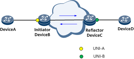
In an Ethernet service activation test, user network interfaces (UNIs) function as measurement points (MPs) to test networks between network-side UNIs shown in Figure 2. The test can be conducted in inward mode so that an initiator within a tested network simulates user access traffic on a network-side UNI. The reflector that has the loopback function enabled can be a tester or another network edge device.
The inward test is cost effective, and all its test functions are implemented on network edge devices, requiring only one tester, or no additional tester at all. In an inward test, a network edge device (initiator) must have the capability to simulate an access interface that sends packets. As the path through which simulated packets pass is different from the actual path, test results may deviate from the parameter settings.
Packet sending mode
The one-way sending mode is used in an Ethernet service activation test. One or more UNIs can send packets to a single reflector. Upon receipt of these packets, the reflector loops packets to these UNIs, and these UNIs calculate and display test results.
One-way packet transmission can be implemented if Y.1564 is enabled on tested devices, regardless of whether their clocks are synchronized. However, one-way packet transmission has the following deficiencies:
Reflection (loopback) must be enabled on the reflector. Looping back packets, including test packets and services, adversely affects services. After the loopback function is enabled on an interface on a reflector, the interface reflects all packets matching the configured service attributes. If the interface is also transmitting other services, the forwarding of these services is adversely affected.

The service traffic attributes include the source MAC address, destination MAC address, VLAN IDs, and priorities (such as 802.1p and DSCP).
In a one-way test, the forward and reverse paths are different. Therefore, measurement errors occur if path configurations, including the link transmission rate, traffic template, quality of service (QoS) parameters, and route parameters, are inconsistent.
Overload or burst tests in inward mode may lower the transmission performance of other services and may produce inaccurate test results.
An inward test cannot verify all SLA performance indexes. Use the inward mode only if you do not have high precision requirements, the number of testers is insufficient, or onsite test operations are difficult to perform.
Test report
An NMS delivers test configurations to an initiator, and the initiator conducts a test and reports results to the NMS. The NMS collects data and displays it on a web page. The initiator also supports command lines used to conduct tests and displays test results.
Table 1 compares performance indicators provided in the generalflow and Ethernet service activation test reports.
Performance Indicator |
Generalflow Test |
Ethernet Service Activation Test |
|---|---|---|
Network throughput |
Maximum transmission rate |
|
Delay |
Average delay |
|
Packet loss ratio |
Packet loss ratio |
Same as the packet loss ratio of a generalflow test |
Jitter |
|
|
Test Procedure
- Configuration tests verify Ethernet service provision, and a configuration test is generated for each service flow.
- Performance tests are simultaneously generated for all service flows, and each test instance is conducted based on the configured maximum CIR. A performance test takes a longer period of time to complete than a configuration test.
Configuration tests
Configuration tests include CIR, EIR, and traffic policing tests.
CIR tests
CIR tests include simple and step CIR tests. Table 2 describes CIR test methods and their advantages.
Table 2 CIR test methods and advantages Test Method
Description
Advantages
Simple CIR test
- An initiator periodically sends test packets at the specified CIR.
- A reflector loops the test packets back. Upon receipt, the initiator calculates performance counters, including the FLR, FTD, and FDV.
- If the calculated FLR, FTD, and FDV are within the configured SAC range, the test is successful, and the EIR test starts. If the calculated counters are out of the configured SAC range, the test fails, and the follow-up tests will not start.
The test speed is fast, and the test process is short.
Step CIR test
- An initiator periodically sends test packets at 25%, 50%, 75%, and 100% of the configured CIR.
- A reflector loops the test packets back. The initiator receives test packets looped by the reflector and calculate the IR, FLR, FTD, and FDV at each rate.
- If the calculated counters are within the configured SAC range, the test is successful, and the next test can be conducted. If the calculated counters are out of the configured SAC range, the test fails, and the whole test stops.
- If all tests are successful, the CIR test is successful, and the EIR test is conducted.
A step CIR test provides more accurate network status analysis, whereas the test time is longer than that of a simple CIR test.
EIR test
EIR tests are conducted in either color-aware or color-blind mode. Table 3 describes EIR test methods and advantages.
Table 3 EIR test methods and advantages Test Method
Description
Advantages
Color-aware mode
- An initiator periodically sends test packets marked green at the specified CIR and test packets marked yellow at the specified EIR.
- A reflector loops the test packets back. Upon receipt, the initiator calculates performance counters, including the FLR, FTD, and FDV.
- If the FLR, FTD, and FDV are within the configured SAC range, the EIR test is successful, and a traffic policing test is then conducted. If the counters are out of the configured SAC range, the EIR test fails. The EIR and the whole test stop.
NOTE:In this mode, only green test packets, not yellow ones, are verified.
Color-aware mode: If the same service implements various applications, application-specific frames can be colored based on performance sensitivities.
Color-blind mode
- An initiator periodically sends test packets at a rate equal to the sum of the configured CIR and EIR.
- A reflector loops the test packets back. Upon receipt, the initiator calculates performance counters, including the IR, FLR, FTD, and FDV.
If the test results satisfy the following formula, the test is successful, and a traffic policing test is then conducted:
CIR x (1 - FLRSAC) ≤ IR ≤ CIR + EIR
If the counters are out of the configured SAC range, the EIR test fails. The EIR and the whole test stop.
NOTE:FLRSAC is the configured FLR, and the IR is the calculated IR.
A carrier network device processes traffic based on the "First In First Processed" rule, regardless of colors.
If the EIR is set to 0 kbit/s, the EIR test is not conducted, and a traffic policing test is performed.
Traffic policing test
Traffic policing tests are conducted using either the color-aware or color-blind mode. Table 4 describes traffic policing test methods and advantages.
Table 4 Traffic policing test methods and advantages Test Method
Description
Advantages
Color-aware mode
- An initiator periodically sends test packets marked green at the specified CIR and test packets marked yellow at 125% of the specified EIR. If the EIR is less than 20% of the configured CIR, the initiator sends test packets marked green at 100% of the configured CIR and test packets marked yellow at the sum rate of 25% of the configured CIR and 100% of the configured EIR.
- A reflector loops the test packets back.
If the FLR, FTD, and FDV are within the configured SAC range, and the test results meet the following formula, the test is successful, and a performance test can be conducted:
CIR x (1 - FLRSAC) ≤ IR ≤ CIR + EIR + M
If the counters are out of the configured SAC range, the traffic policing test fails. The traffic policing and the whole test stop.
NOTE:In this mode, only green test packets, not yellow ones, are verified.
Color-aware mode: Application-specific frames in the same test instance can be colored based on performance sensitivities.
Color-blind mode
- An initiator periodically sends test packets at the sum rate of the configured CIR and 125% of the configured EIR. If the configured EIR is less than 20% of the configured CIR, the initiator sends test packets at a sum rate of the configured EIR and 125% of the CIR.
- A reflector loops the test packets back. Upon receipt, the initiator calculates performance counters, including the IR, FLR, FTD, and FDV.
If the test results satisfy the following formula, the test is successful, and a traffic policing test is then conducted:
CIR x (1 - FLRSAC) ≤ IR ≤ CIR + EIR + M
If the counters are out of the configured SAC range, the traffic policing test fails. The traffic policing and the whole test stop.
NOTE:M is a factor used to strike a balance between traffic policing and the test time. M is an experience value and is not defined in Y.1564. It is set to (CIR + EIR) x 1% in this document.
A carrier network device processes traffic based on the "First In First Processed" rule, regardless of colors.
If the traffic policing test for NQA test flows is disabled, a performance test is conducted immediately.
Performance test
A device automatically starts a performance test only after the configuration tests, including the CIR, EIR, and traffic policing tests, are complete.
In a performance test, an initiator simultaneously sends test packets for all service flows at the specified CIR.
A reflector loops the test packets back. Upon receipt, the initiator calculates performance counters, including the IR, FLR, FTD, and FDV for each service flow. If the counters are within the configured SAC range, the performance test for a service flow is successful. If the counters are out of the configured SAC range, the performance for the service flow fails.
During an Ethernet service activation test, modifying the system time of the testing device may affect the test duration and accuracy of the test result. Therefore, modifying the system time of a testing device is not recommended.
Usage Scenarios
- Layer 2 scenarios (the destination MAC address is specified in a test to check the performance of a network between the initiator and reflector):
- Native Ethernet
- L2VPN/EVPN L2VPN
- EVPN VXLAN
- Layer 3 scenarios (the destination IP address is specified in a test to check the performance of a network between the initiator and reflector):
- Native IP
- L3VPN/EVPN L3VPN
- EVPN VXLAN
- HVPN
- L2VPN accessing L3VPN (The destination IP address is specified in a test to check the performance of a network between the L2VPN and L3VPN.)
SRv6 tunnels (including SRv6 BE and SRv6 TE Policy) are supported only in the following scenarios:
- EVPN L2VPN
- L3VPN/EVPN L3VPN
- HVPN
- EVPN L2VPN + EVPN L3VPN
Benefits
Ethernet service activation tests provide accurate test results that can reliably reflect the performance of networks that carriers lease to customers. Therefore, Ethernet service activation tests helps carriers verify that network quality meets requirements before service provision on networks when only limited-accuracy tests are needed, tests devices are sufficient, or onsite operations are difficult to perform.