RFC 2544 Generalflow Test
Overview
An NQA generalflow test is a standard traffic testing method for evaluating network performance and is in compliance with RFC 2544. This test can be used in various networking scenarios that have different packet formats. NQA generalflow tests are conducted using UDP packets with source UDP port 49184 and destination UDP port 7.
Enables a device to send simulated service packets to itself before services are deployed on the device.
Existing methods include Y.1731 on Layer 2 networks and IP Flow Performance Management (IP FPM) on Layer 3 networks. These methods, unlike generalflow tests, can only be used when services have been deployed on networks. If no services are deployed, testers must be used to send and receive test packets.
Uses standard methods and procedures that comply with RFC 2544 so that NQA generalflow tests can be conducted on a network on which both Huawei and non-Huawei devices are deployed.
Test Procedure
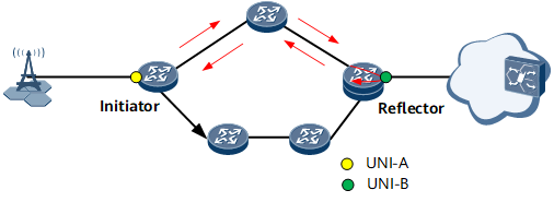
A generalflow test is an NQA test tool using UDP packets. An initiator (NQA client) initiates a generalflow test and sends test packets to a reflector. After the test packets arrive at the reflector, the reflector interchanges the source and destination addresses in the packets and loops the packets to the initiator. The initiator counts the number of sent and received packets and calculates indicators based on timestamps carried in the packets.
A generalflow test measures the following counters:
- Throughput: maximum rate at which packets are sent without loss.
Packet loss rate: percentage of discarded packets to all sent packets.
Latency: consists of the bidirectional delay time and jitter calculated based on the transmission and receipt timestamps carried in test packets. The transmission time in each direction includes the time the forwarding devices process the test packet.
These counters are calculated in separate tests. A counter must be specified before a test is conducted.
On the network shown in Figure 1, UNI-A is an initiator, and UNI-B is a reflector. UNI-A and UNI-B conduct tests on the throughput, delay time, and packet loss rate.
Throughput tests
Throughput tests are conducted to test throughput values by sending test packets at rates of the specified upper and lower rate thresholds or at rates in between. The difference between the test result and actual throughput must be less than a specified precision value. The test procedure is as follows:
- The initiator sends test packets at a rate equal to the upper threshold. The network bandwidth is acceptable if no packet is dropped within a specified period or the packet loss rate is less than the configured test failure percentage. Then the test continues.
- An initiator sends test packets at a rate equal to the lower threshold. The network bandwidth is acceptable if no packet is dropped within a specified period or the packet loss rate is less than the configured packet loss rate. Then the test continues.
If the packet loss rate tested based on the upper limit does not meet the customer expectation, conduct another test with a test rate obtained using the following formula: Upper limit test rate x (1 – Packet loss rate).
Latency tests
Latency tests can only be conducted when background traffic is being transmitted. An initiator sends background traffic at a specific rate and test packets at a specific interval to a reflector. The initiator then calculates the bidirectional delay time and jitter based on the transmission and receipt time.
Packet loss rate tests
An initiator sends test packets at a specific rate and interval to a reflector. Software collects statistics about the sent and received packets every second. The initiator stops sending test packets and counts the number of sent and received packets. The initiator then calculates the packet loss rate based on the statistics.

During a generalflow test, modifying the system time of the testing device may affect the test duration and accuracy of the test result. Therefore, modifying the system time of a testing device is not recommended.
Applications
A generalflow test can be used in the following scenarios:
Layer 2: native Ethernet, L2VPN (VLL and P2P VPLS), EVPN
At present, EVPN supports only the EVPN MPLS scenario, not the EVPN VXLAN scenario.
Layer 3: native IP scenario and Layer 3 virtual private network (L3VPN) scenario
IP gateway scenario
L2VPN accessing L3VPN scenario
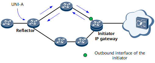
In both the Layer 2 and Layer 3 scenarios, a generalflow test is performed between two UNIs on the network shown in Figure 2. The initiator sends test packets to the reflector. The reflector returns all test packets received by a reflector interface or only returns packets matching a specific filter condition. After the initiator receives the test packets, it collects statistics and yields test results based on the statistics.
On the network shown in Figure 3, a reflector functions as a switch. Layer 3 services on a user-side CE are sent to an IP gateway (initiator) through a Layer 2 network. A generalflow test can be conducted in this scenario. The procedure is similar to that in the Layer 3 scenario.
Unlike the initiator in the Layer 3 scenario, the IP gateway cannot learn the MAC address of the reflector or CE. In this situation, you must configure static ARP entries on both the originator and reflector.
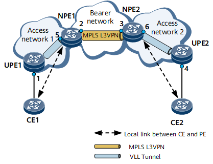
If the initiator and reflector reside in locations 1 and 5 (or 5 and 1), respectively, or the initiator and reflector reside in locations 4 and 6 (or 6 and 4), respectively, it is a native Ethernet scenario.
If the initiator and reflector reside in locations 2 and 3 (or 3 and 2), respectively, it is a native IP scenario.
If the initiator resides in location 3 and the reflector in location 1, or the initiator resides in location 2 and the reflector in location 4, it is similar to an IP gateway scenario, and the simulated IP address must be configured on the L2VPN device.
If the initiator and reflector reside in locations 1 and 2 (or 2 and 1), respectively, or the initiator and reflector reside in locations 3 and 4 (or 4 and 3), respectively, it is an IP gateway scenario.
If the initiator resides in location 1 and the reflector in location 4, the initiator resides in location 1 and the reflector in location 3, or the initiator resides in location 4 and the reflector in location 2, it is an L2VPN accessing L3VPN scenario. In this scenario, the destination IP and MAC addresses and the source IP address must be specified on the initiator, and the destination IP address for receiving test flows must be specified on the reflector. If the initiator resides on the L2VPN, the simulated IP address must be specified as the source IP address.