ERPS Multi-Ring Fundamentals
Ethernet Ring Protection Switching version 1 (ERPSv1) supports only the single-ring topology, whereas ERPSv2 supports both single- and multi-ring topologies.
In a multi-ring topology, there are major rings and sub-rings. Depending on whether Ring Auto Protection Switching Protocol Data Units (R-APS PDUs) on a sub-ring are transmitted to a major ring, a sub-ring may either have or not have a virtual channel (VC). If R-APS PDUs on a sub-ring are transmitted to a major ring, the sub-ring has a VC; otherwise, the sub-ring does not have a VC.
This section describes how ERPS works when links are normal, when a link fails, and when the link recovers on a multi-ring network with sub-rings that do not have VCs or have VCs.
Sub-rings Do Not Have VCs
In this situation, R-APS PDUs of sub-rings are terminated on interconnection nodes, instead of being transmitted to the major ring. The blocked ports of the sub-rings block only data traffic rather than the R-APS PDUs.
Links Are Normal
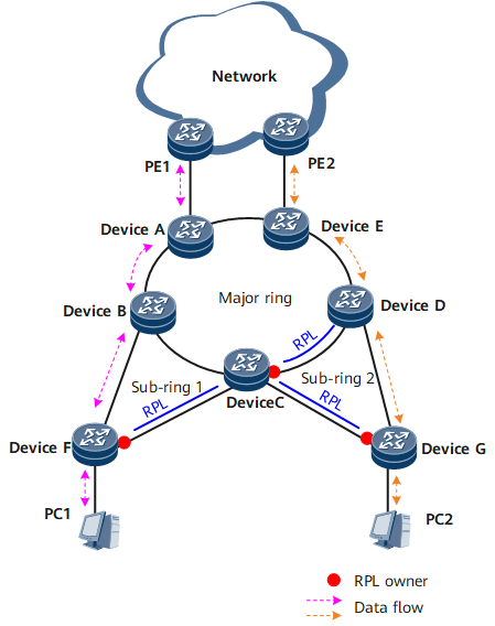
On the multi-ring network shown in Figure 1, Device A through Device E constitute a major ring; Device B, Device C, and Device F constitute sub-ring 1, and Device C, Device D, and Device G constitute sub-ring 2. The devices on each ring can communicate with each other.
- To prevent loops, each ring blocks its Ring Protection Link (RPL) owner port. All other ports can transmit data traffic.
- The RPL owner port on each ring sends R-APS (NR) messages to all other nodes on the same ring at an interval of 5s. The R-APS (NR) messages on the major ring are transmitted only on this ring. The R-APS (NR) messages on each sub-ring are terminated on the interconnection nodes and therefore are not transmitted to the major ring.
Traffic between PC1 and the upper-layer network travels along the path PC1 <-> Device F <-> Device B <-> Device A <-> PE1; traffic between PC2 and the upper-layer network travels along the path PC2 <-> Device G <-> Device D <-> Device E <-> PE2.
A Link Fails
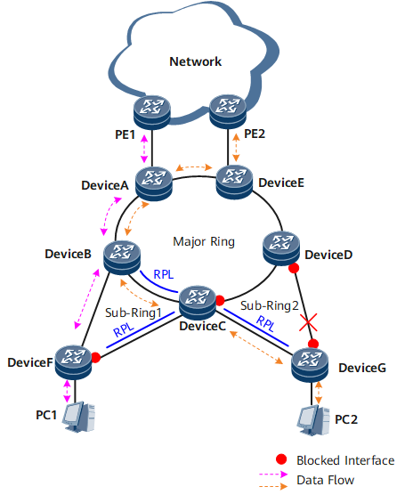
In Figure 2, if the link between Device D and Device G fails, ERPS is triggered. Specifically, the ports on both ends of the faulty link are blocked, and the RPL owner port on sub-ring 2 is unblocked to send and receive user traffic. In this situation, traffic from PC1 is not interrupted and still travels along the original path. Device C and Device D inform the other nodes on the major ring of the topology change so that traffic from PC2 is also not interrupted. Traffic between PC2 and the upper-layer network travels along the path PC2 <-> Device G <-> Device C <-> Device B <-> Device A <-> Device E <-> PE2. The detailed process is as follows:
- After Device D and Device G detect the link fault, they both block their ports on the faulty link and perform a Filtering Database (FDB) flush.
- Device G sends three consecutive R-APS (SF) messages to the other devices on sub-ring 2 and then sends one R-APS (SF) message at an interval of 5s afterwards.
- Device G unblocks the RPL owner port and performs an FDB flush.
- After the interconnection node Device C receives an R-APS (SF) message, it performs an FDB flush. Device C and Device D then send R-APS Event messages within the major ring to notify the topology change of sub-ring 2.
- After receiving an R-APS Event message, the other major ring nodes perform an FDB flush. Traffic from PC2 is then rapidly switched to a normal link.
The Link Recovers
After the link fault is rectified, either of the following situations may occur:
- If the revertive switching mode is configured for the ERPS major and sub-rings, the RPL owner port is blocked again, and the link that has recovered is used to forward traffic.
- If the non-revertive switching is configured for the ERPS major and sub-rings, the RPL owner port remains unblocked, but the link that has recovered remains blocked.
The following example uses revertive switching to describe the process after the link recovers.
- After the link between Device D and Device G recovers, Device D and Device G start a guard timer to avoid receiving out-of-date R-APS PDUs. The two routers do not receive any R-APS PDUs before the timer expires. Device D and Device G then send R-APS (NR) messages within sub-ring 2.
- Device G on which the RPL owner port resides starts the WTR timer. After the WTR timer expires, Device G blocks the RPL owner port, unblocks its port on the link that has recovered, and then sends R-APS (NR, RB) messages within sub-ring 2.
- After receiving an R-APS (NR, RB) message from Device G, Device D unblocks its port on the recovered link, stops sending R-APS (NR) messages, and performs an FDB flush. Device C also performs an FDB flush.
- Device C and Device D, the interconnection nodes, send R-APS Event messages within the major ring to notify the link recovery of sub-ring 2.
- After receiving an R-APS Event message, the other major ring nodes perform an FDB flush.
Traffic from PC2 then travels in the same way as that shown in Figure 1.
Sub-rings Have VCs
When sub-rings have VCs, the R-APS PDUs of the sub-rings are transmitted to the major ring through the interconnection nodes. In other words, the interconnection nodes do not terminate the R-APS PDUs of the sub-rings. The blocked ports of sub-rings block both R-APS PDUs and data traffic.
Links Are Normal
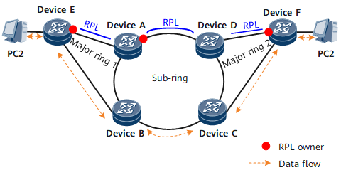
On the multi-ring network shown in Figure 3, Device A, Device B, and Device E constitute major ring 1; Device C, Device D, and Device F constitute major ring 2; Device A through Device D constitute a sub-ring. The two major rings are interconnected with the sub-ring. The devices on each ring can communicate with each other.
- To prevent loops, each ring blocks its RPL owner port. All other ports can transmit data traffic.
- The RPL owner port on each ring sends R-APS (NR) messages to all other nodes on the same ring at an interval of 5s. The R-APS (NR) messages of each major ring are transmitted only within the same major ring, whereas the R-APS (NR) messages of the sub-ring are transmitted to the major rings over the interconnection nodes.
Traffic between PC1 and PC2 travels along the path PC1 <-> Device E <-> Device B <-> Device C <-> Device F <-> PC2.
A Link Fails
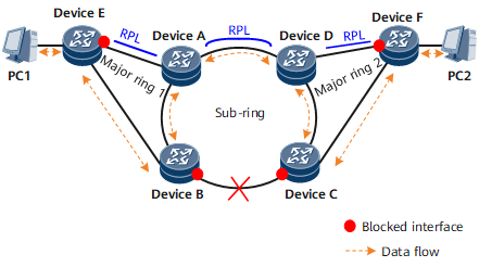
As shown in Figure 4, if the link between Device B and Device C fails, ERPS is triggered. Specifically, the ports on both ends of the faulty link are blocked, and the RPL owner port on the sub-ring is unblocked to send and receive user traffic. Device B and Device C inform the other nodes on the major rings of the topology change so that traffic between PCs is not interrupted. Traffic between PC1 and PC2 then travels along the path PC1 <-> Device E <-> Device B <-> Device A <-> Device D <-> Device C <-> Device F <-> PC2. The detailed process is as follows:
- After Device B and Device C detect the link fault, they both block their ports on the faulty link and perform an FDB flush.
- Device B sends three consecutive R-APS (SF) messages to the other devices on the sub-ring and then sends one R-APS (SF) message at an interval of 5s afterwards. The R-APS (SF) messages then arrive at major ring 1.
- After receiving an R-APS (SF) message, Device A on major ring 1 unblocks its RPL owner port and performs an FDB flush.
- The other major ring nodes also perform an FDB flush. Traffic between PCs is then rapidly switched to a normal link.
The Link Recovers
After the link fault is rectified, either of the following situations may occur:
- If the revertive switching mode is configured for the ERPS major rings and sub-ring, the RPL owner port is blocked again, and the link that has recovered is used to forward traffic.
- If the non-revertive switching is configured for the ERPS major rings and sub-ring, the RPL owner port remains unblocked, but the link that has recovered remains blocked.
The following example uses revertive switching to describe the process after the link recovers.
- After the link between Device B and Device C recovers, Device B and Device C start a guard timer to avoid receiving out-of-date R-APS PDUs. The two routers do not receive any R-APS PDUs before the timer expires. Then Device B and Device C send R-APS (NR) messages, which are transmitted within the major rings and sub-ring.
- Device A starts the WTR timer. After the WTR timer expires, Device A blocks the RPL owner port and then sends R-APS (NR, RB) messages to other connected devices.
- After receiving an R-APS (NR, RB) message from Device A, Device B and Device C unblock its port on the recovered link, stop sending R-APS (NR) messages, and perform an FDB flush.
- After receiving an R-APS (NR, RB) message from Device A, other devices also perform an FDB flush.
Traffic then travels in the same way as that shown in Figure 3.