HVPN
Background
Provide access services for users. This function requires each PE to provide a large number of interfaces.
Manage and advertise VPN routes and process user packets. This function requires each PE to have a high-capacity memory and strong forwarding capabilities.
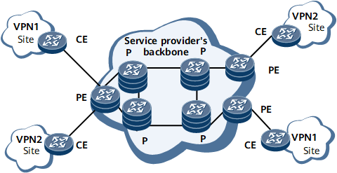
To deploy VPN functions in a hierarchical architecture, a BGP/MPLS IP VPN must use a hierarchical model instead of a plane model. As a result, the concept of HVPN is introduced.
Related Concepts
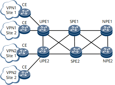
- UPE: a type of PE directly connected to CEs and provides access services for users.
- SPE: a type of PE connected to UPEs and located on the core of a network. SPEs manage and advertise VPN routes.
- NPE: a type of PE connected to SPEs and located on the network side.
A UPE and an SPE are connected by only one link and exchange packets based on labels. An SPE does not need to provide a large number of interfaces for access users. UPEs and SPEs can be connected by physical interfaces with physical links, by sub-interfaces with VLANs or PVCs, or by tunnel interfaces with LSPs. If an IP or MPLS network resides between a UPE and an SPE, the UPE and SPE can be connected by tunnel interfaces to exchange labeled packets over a tunnel.
The capabilities of SPEs and UPEs differ according to the roles they play on a network. SPEs require large-capacity routing tables and high forwarding performance, but few interface resources. UPEs, on the other hand, require only low-capacity routing tables and low forwarding performance, but high access capabilities.

The roles of UPEs and SPEs are relative. On an HVPN, a superstratum PE is the SPE of an understratum PE, and an understratum PE is the UPE of a superstratum PE.
An HoPE is compatible with common PEs on an MPLS network.
If a UPE and an SPE belong to the same AS, they use MP-IBGP. If they belong to different ASs, they use MP-EBGP.
If MP-IBGP is used, an SPE can function as the RR for multiple UPEs to advertise routes between IBGP peers. To reduce the number of routes on UPEs, ensure that an SPE that is already acting as the RR for UPEs is not used as the RR for other PEs.
HVPN can be classified into HoVPN and H-VPN.
HVPN Mode |
Characteristics |
|---|---|
HoVPN |
An SPE advertises only default or aggregated routes to UPEs.
|
H-VPN |
An SPE advertises all VPN routes to UPEs.
|
The following describes the route exchanging and packet forwarding processes on an HoVPN and an H-VPN. In the following figures, N indicates a next hop, and L indicates a label.
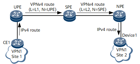
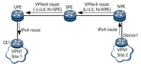
Route Advertisement from CE1 to Device1 on an HoVPN or H-VPN
CE1 advertises IPv4 routes to the UPE using the IP protocol.
The UPE applies for label L1 for the received IPv4 routes and converts these routes to VPNv4 routes. Then, the UPE sets itself as the next hops of these routes and advertises them to the SPE.
After receiving the VPNv4 routes, the SPE saves label L1 locally and applies for label L2 for these VPNv4 routes. Then, the SPE sets itself as the next hops of these routes and advertises them to the NPE.
After receiving the VPNv4 routes, the NPE converts these routes to IPv4 routes and imports routes with reachable next hops to its VPN IPv4 routing table. The NPE retains label L2 and recursive tunnel ID information of these routes for later packet forwarding.
The NPE advertises the IPv4 routes to Device1 using the IP protocol.
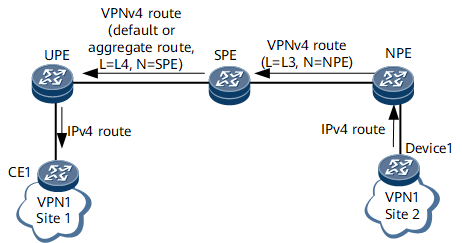
Route Advertisement from Device1 to CE1 on an HoVPN
Device1 advertises IPv4 routes to the NPE using the IP protocol.
The NPE applies for label L3 for the received IPv4 routes and converts these routes to VPNv4 routes. Then, the NPE sets itself as the next hops of these routes and advertises them to the SPE.
After receiving the VPNv4 routes, the SPE saves label L3 locally and converts these routes to IPv4 routes and imports routes with reachable next hops to its VPN IPv4 routing table.
The SPE imports a default route to its VPN IPv4 routing table or generates an aggregated VPN route based on the received IPv4 routes in its VPN IPv4 routing table and applies for label L4 for the default route or aggregated VPN route. Then, the SPE converts the default route or aggregated VPN route to a VPNv4 route, sets itself as the next hop of the VPNv4 route, and advertises the route to the UPE.
After receiving the VPNv4 route, the UPE converts the route to an IPv4 route and imports the route to its VPN IPv4 routing table if the next hop of the route is reachable.
The UPE advertises the IPv4 route to CE1 using the IP protocol.
Route Advertisement from Device1 to CE1 on an H-VPN
Device1 advertises IPv4 routes to the NPE using the IP protocol.
The NPE applies for label L3 for the received IPv4 routes and converts these routes to VPNv4 routes. Then, the NPE sets itself as the next hops of these routes and advertises them to the SPE.
After receiving the VPNv4 routes, the SPE saves label L3 locally and applies for label L4 for these VPNv4 routes. Then, the SPE sets itself as the next hops of these routes and advertises them to the UPE.
After receiving the VPNv4 routes, the UPE converts these routes to IPv4 routes and imports routes with reachable next hops to its VPN IPv4 routing table.
The UPE advertises the IPv4 routes to CE1 using the IP protocol.
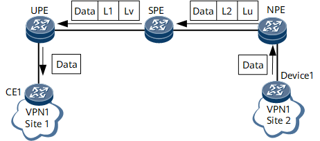
Packet Forwarding from Device1 to CE1 on an HoVPN or H-VPN
Device1 sends a VPN packet to the NPE.
After receiving the packet, the NPE searches its VPN forwarding table for a tunnel to forward the packet based on the destination address of the packet. Then, the NPE adds an inner label L2 and an outer label Lu to the packet and sends the packet to the SPE over the found tunnel.
After receiving the packet, the SPE replaces the outer label Lu with Lv and the inner label L2 with L1. Then, the SPE sends the packet to the UPE over the same tunnel.
After receiving the packet, the UPE removes the outer label Lv, searches for a VPN instance corresponding to the packet based on the inner label L1, and removes the inner label L1 after the VPN instance is found. Then, the UPE searches the VPN forwarding table of this VPN instance for the outbound interface of the packet based on the destination address of the packet and sends the packet through this outbound interface to CE1. The packet sent by the UPE is a pure IP packet with no label.
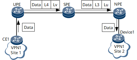
Packet Forwarding from CE1 to Device1 on an HoVPN
CE1 sends a VPN packet to the UPE.
After receiving the packet, the UPE searches its VPN forwarding table for a tunnel to forward the packet based on the destination address of the packet (the UPE does so by matching the destination address of the packet against the forwarding entry for the default route or aggregated route). Then, the UPE adds an inner label L4 and an outer label Lv to the packet and sends the packet to the SPE over the found tunnel.
After receiving the packet, the SPE removes the outer label Lv and searches for the VPN instance corresponding to the packet based on the inner label L4. Then, the SPE removes the inner label L4 and searches the VPN forwarding table of the found VPN instance for a tunnel to forward the packet based on the destination address of the packet. Finally, the UPE adds an inner label L3 and an outer label Lu to the packet and sends the packet to the NPE over the found tunnel.
After receiving the packet, the NPE removes the outer label Lu, searches for a VPN instance corresponding to the packet based on the inner label L3, and removes the inner label L3 after the VPN instance is found. Then, the NPE searches the VPN forwarding table of this VPN instance for the outbound interface of the packet based on the destination address of the packet and sends the packet through this outbound interface to Device1. The packet sent by the NPE is a pure IP packet with no label.
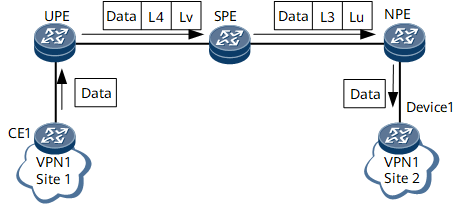
Packet Forwarding from CE1 to Device1 on an H-VPN
CE1 sends a VPN packet to the UPE.
After receiving the packet, the UPE searches its VPN forwarding table for a tunnel to forward the packet based on the destination address of the packet (the UPE does so by matching the destination address of the packet against the forwarding entries for specific routes received from the SPE). Then, the UPE adds an inner label L4 and an outer label Lv to the packet and sends the packet to the SPE over the found tunnel.
After receiving the packet, the SPE replaces the outer label Lv with Lu and the inner label L2 with L3. Then, the SPE sends the packet to the NPE over the same tunnel.
After receiving the packet, the NPE removes the outer label Lu, searches for a VPN instance corresponding to the packet based on the inner label L3, and removes the inner label L3 after the VPN instance is found. Then, the NPE searches the VPN forwarding table of this VPN instance for the outbound interface of the packet based on the destination address of the packet and sends the packet through this outbound interface to Device1. The packet sent by the NPE is a pure IP packet with no label.
Related Functions
H-VPN supports HoPE embedding:
You can connect a new SPE to an existing SPE and configure the existing SPE to be the UPE of the new SPE.
You can connect a new UPE to an existing UPE and configure the existing UPE to be the SPE of the new UPE.
HoPEs can be embedded repeatedly in the preceding two methods.
HoPE embedding can infinitely expand a VPN in theory.
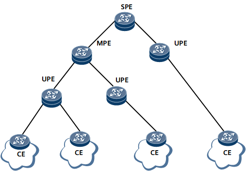
Figure 9 shows a three-layer H-VPN, and the PEs in the middle are referred to as middle-level PEs (MPEs). MP-BGP runs between the SPE and MPEs, and between the MPEs and UPEs.
The MPE concept is introduced solely for descriptive purposes and does not actually exist in an H-VPN model.
MP-BGP advertises all the VPN routes of UPEs to the SPE, but advertises only the default routes of the VPN instances of the SPE to UPEs.
An SPE maintains the routes of all VPN sites connected to its understratum PEs, whereas a UPE maintains only the routes of its directly connected VPN sites. The numbers of routes maintained by an SPE, an MPE, and a UPE are in descending order.
Benefits
HVPN networking offers the following benefits:
Flexible expansibility
If the performance of a UPE is insufficient, you can add an SPE for the UPE to access. If the access capabilities of an SPE are insufficient, add more UPEs to the SPE.
Reduced interface resource requirements
Since a UPE and an SPE exchange packets based on labels, they only need to be connected over a single link.
Reduced burdens on UPEs
A UPE needs to maintain only local VPN routes. The remote VPN routes are represented by a default or aggregated route, lightening the burdens on UPEs.
Simpler configuration
SPEs and UPEs use MP-BGP, a dynamic routing protocol, to exchange routes and advertise labels. Each UPE only needs to establish a single MP-BGP peer relationship with an SPE.