Carrier's Carrier
Background
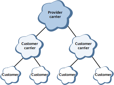
A customer of an SP providing BGP/MPLS IP VPN services may also be an SP. In this case, the SP providing the BGP/MPLS VPN service is called the provider carrier or Level 1 carrier and the customer is called the customer carrier or Level 2 carrier, as shown in Figure 1. This networking model is called carrier's carrier. In this model, the Level 2 carrier is a VPN user of the Level 1 carrier.
Related Concepts
To ensure good expansibility, the Level 2 carrier uses an operation mode similar to that of a stub VPN. In other words, the Level 1 carrier CE advertises only Level 2 carrier's internal routes, instead of the Level 2 carrier routes, to the Level 1 carrier PE. In this section, the internal and external routes of the Level 2 carrier are called internal and external routes for short, respectively.
The differences between internal and external routes are as follows:
Routes to Level 2 carrier SP sites are called internal routes. The routes to VPNs of the Level 2 carrier are called external routes.
Level 1 carrier PEs exchange internal routes using BGP. The external routes are exchanged using BGP between Level 2 carrier PEs, but are not advertised to Level 1 carrier PEs.
The VPN-IPv4 routes of the Level 2 carrier are considered as external routes. The Level 2 carrier PEs import only internal routes and not external routes to their VRFs, reducing the number of routes that need to be maintained on the Level 1 carrier network. The Level 2 carrier network has to maintain both internal and external routes.

A Level 1 carrier CE is a device through which the Level 2 carrier network accesses the Level 1 carrier network. The Level 1 carrier CE means a CE for a Level 1 carrier network and a PE for a Level 2 carrier network. The device through which users access the Level 2 carrier network is called a user CE.
Scenario Categories
The Level 2 carrier can be a common SP or a BGP/MPLS IP VPN SP.
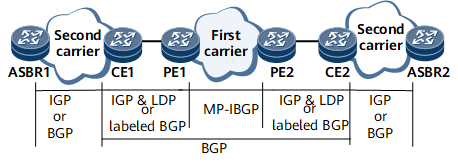
If a Level 2 carrier is a common SP, MPLS does not need to be configured on Level 2 carrier PEs. Level 2 carrier PEs communicate with Level 1 carrier PEs using an IGP. Level 2 carrier PEs exchange external routes with each other over BGP sessions, as shown in Figure 2.
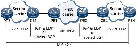
If a Level 2 carrier is a BGP/MPLS IP VPN SP, Level 2 carrier PEs must be configured with MPLS. Level 2 carrier PEs communicate with Level 1 carrier CEs using an IGP and LDP. Level 2 carrier PEs exchange external routes between each other using MP-BGP, as shown in Figure 3.
Classification of Implementation Solutions
When the Level 2 carrier is a common SP, the IP network and the BGP/MPLS IP VPN are co-constructed. The key point is that a BGP peer relationship is re-established after Level 1 carrier CEs can communicate with each other.
When the Level 2 carrier is a BGP/MPLS IP VPN SP, the LDP multi-instance solution is called carrier's carrier solution 1 and the BGP label routing solution is called carrier's carrier solution 2 according to the method that the Level 2 carrier CE uses to access the Level 2 carrier PE.
The scenario where the Level 2 carrier is a BGP/MPLS IP VPN SP is more commonly used. The scenario where the Level 2 carrier is a common SP is seldom used and the configuration scheme is simple. Therefore, the following description focuses on the scenario where the Level 2 carrier is a BGP/MPLS IP VPN SP.
Carrier's Carrier Solution 1 (LDP Multi-Instance)
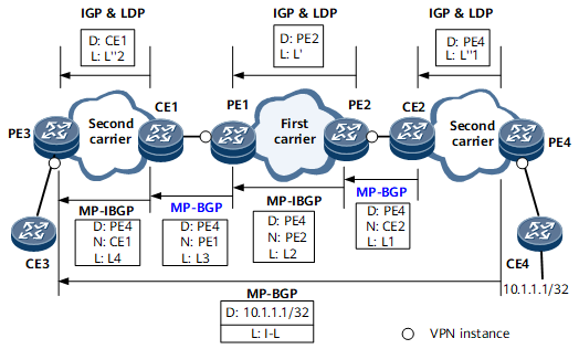
When the Level 1 carrier CE uses the LDP multi-instance to set up an LDP LSP to access the Level 1 carrier PE, the routing information exchange process is shown in Figure 4. D represents the destination address of a route, N the next hop, and L the label.
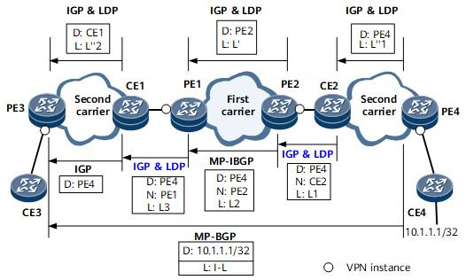
The following uses the advertisement of a VPN route destined for 10.1.1.1/32 advertised by PE4 to PE3 as an example to describe VPN route exchange inside the Level 2 carrier network.
PE4 advertises a route destined for itself to CE2 using an IGP running on the Level 2 carrier network. Meanwhile, PE4 assigns label L''1 to the IGP next hop and establishes a public network LSP to CE2.
CE2 advertises the route destined for PE4 to PE2 using an IGP running between CE2 and PE2. In addition, LDP is used to allocate label L1 to the route. (LDP multi-instance needs to be configured on PE2's interface connected to CE2.)
PE2 assigns label L2 to the route destined for PE4 and advertises the route to PE1 using MP-IBGP. Previously, PE2 has advertised its routes to PE1 using an IGP running on the Level 1 carrier backbone network and assigned label L' to the routes destined for itself. A public network LSP has been established between PE2 and PE1.
PE1 assigns label L3 to the route destined for PE4 based on the LDP multi-instance peer relationship with CE1, and advertises the route carrying label L3 to CE1.
CE1 uses an IGP to advertise the route to PE4 to PE3.
Previously, CE1 has advertised its routes to PE3 using an IGP running on the Level 2 carrier backbone network and assigned label L''2 to the routes destined for itself. A Level 2 public network LSP has been established between CE1 and PE3.
After the route destined for PE3 is advertised to PE4, an MP-IBGP connection is established between PE3 and PE4.
PE4 assigns VPN label I-L to the VPN route destined for 10.1.1.1/32 and advertises the route to PE3 using MP-IBGP.
The advertisement of a VPN route from PE3 to PE4 is similar to that from PE4 to PE3 and therefore is not described here.
Figure 5 shows the transmission of VPN packets on the carrier network. I-L indicates a VPN label assigned by MP-BGP. L' indicates the public network label used on the Level 1 carrier network. L''1 and L''2 stand for public network labels used on the Level 2 carrier network. L1, L2, and L3 represent labels assigned to packets destined for PE4.
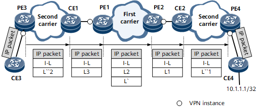
The following uses forwarding of the VPN packet destined for 10.1.1.1/32 from PE3 to CE4 as an example to describe VPN packet forwarding over carrier networks.
After receiving a VPN packet destined for 10.1.1.1/32, PE3 adds the VPN label I-L to this packet and transparently transmits the packet to CE1 over the public network LSP on the Level 2 carrier network.
Before the packet arrives at CE1, the penultimate LSR removes the outer public network label of the packet.
CE1 adds label L3 to the packet and forwards this packet to PE1.
PE1 replaces label L3 with label L2 and adds label L' to the packet. PE1 then forwards the packet to PE2 over the public network LSP. Before the packet arrives at PE2, the penultimate LSR removes label L'.
PE2 replaces label L2 with label L1 and forwards the packet to CE2.
CE2 removes label L1, adds label L''1, and transparently forwards the packet to PE4 over the public network LSP on the Level 2 carrier network.
Before the packet arrives at PE4, the penultimate LSR removes label L''1.
PE4 removes label I-L and forwards the packet to CE4 based on label I-L.
Carrier's Carrier Solution 2 (BGP Labeled Route)
Figure 6 shows the route exchange process when the Level 1 carrier CE uses the BGP labeled route solution to establish a BGP LSP and accesses the Level 1 carrier PE. D represents the destination address of a route, N the next hop, and L the label.
The following uses the advertisement of a VPN route destined for 10.1.1.1/32 from PE4 to PE3 as an example to describe VPN route exchange inside the Level 2 carrier network.
PE4 advertises a route destined for itself to CE2 using an IGP running on the Level 2 carrier network. Meanwhile, PE4 assigns label L''1 to the IGP next hop and establishes a public network LSP to CE2.
CE2 assigns label L1 to the route to PE4 based on the MP-BGP peer relationship with PE2, and advertises the labeled route to PE2.
PE2 assigns label L2 to the route and advertises the route destined for PE4 to PE1 using MP-IBGP.
Previously, PE2 has advertised its routes to PE1 using an IGP running on the Level 2 carrier's backbone network and assigned label L' to the routes destined for itself. A public network LSP has been established between PE2 and PE1.
PE1 assigns label L3 to the route destined for PE4 based on the MP-BGP peer relationship with CE1, and advertises the route carrying label L3 to CE1.
CE1 assigns label L4 to the route destined for PE4, and advertises the route carrying label L4 to PE3 through the MP-IBGP peer relationship between CE1 and PE3.
Previously, CE1 has advertised its route to PE3 using an IGP running on the Level 2 carrier backbone network and assigned label L''2 to the route destined for itself. A Level 2 public network LSP has been established between CE1 and PE3.
The route destined for PE4 and label assigned to the route are advertised to PE3. A BGP LSP is established between CE2 and PE3.
After the route destined for PE3 is advertised to PE4, an MP-EBGP connection is successfully established between PE3 and PE4.
PE4 assigns VPN label I-L to the VPN route destined for 10.1.1.1/32 and advertises the route to PE3 using MP-EBGP.
The advertisement of the VPN route from PE3 to PE4 is similar to that from PE4 to PE3 and therefore is not described here.
Figure 7 shows the transmission of VPN packets on the carrier network. I-L represents the VPN label assigned using MP-BGP. L' indicates the public network label used on the Level 1 carrier network. L''1 and L''2 stand for public network labels used on the Level 2 carrier network. L1, L2, L3, and L4 represent labels assigned to packets destined for PE4.
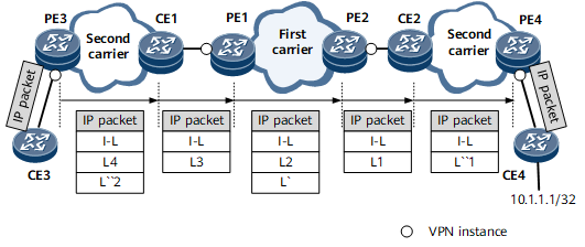
The following uses forwarding of the VPN packet destined for 10.1.1.1/32 from PE3 to CE4 as an example to describe VPN packet forwarding over carrier networks.
After receiving the VPN packet destined for 10.1.1.1/32, PE3 adds the VPN label I-L and BGP LSP label L4 to this packet and transparently forwards the packet to CE1 over the public network LSP on the Level 2 carrier network.
Before the packet arrives at CE1, the penultimate LSR removes the outer public network label of the packet.
CE1 replaces L4 with L3 and forwards the packet to PE1.
PE1 replaces label L3 with label L2, adds label L', and forwards the packet to PE2 over the public network LSP. Before the packet arrives at PE2, the penultimate LSR removes label L'.
PE2 replaces label L2 with label L1 and forwards the packet to CE2.
CE2 removes label L1, adds label L''1, and transparently forwards the packet to PE4 over the public network LSP on the Level 2 carrier network.
Before the packet arrives at PE4, the penultimate LSR removes label L''1.
PE4 removes label I-L and forwards the packet to CE4 based on label I-L.
Benefits
The carrier's carrier model has the following advantages:
Part of the configuration, management, and maintenance work used to be carried out by the Level 2 carrier can be undertaken by the Level 1 carrier.
The Level 2 carrier can flexibly plan addresses, as its addresses are independent of those of the customers and the Level 1 carrier.
The Level 1 carrier can provide VPN services for multiple Level 2 carriers over a backbone network, and can provide Internet services at the same time. This increases the profits of the Level 2 carrier.
The Level 1 carrier manages and maintains VPN services of each Level 2 carrier in the same manner instead of maintaining individual backbone networks for Level 2 carriers. This simplifies the operation of the Level 1 carrier.
The carrier's carrier model has the following disadvantages: As a strict symmetrical networking mode, only VPN users at the same network level can communicate with each other.
VPN users at the same network level need to directly exchange VPN routing information between each other. Therefore, these user devices must be routable. The user devices at the same network level must maintain all routing information of this network level. The PEs at the same network level need to directly exchange VPNv4 routes between each other.