Inter-AS VPN
With the wide application of MPLS VPN solutions, different MANs of a carrier or collaborating backbone networks of different carriers frequently span multiple ASs.
Generally, an MPLS VPN architecture runs within an AS in which VPN routing information is flooded on demand. The VPN routing information within the AS cannot be flooded to the other ASs. To implement exchange of VPN routes between different ASs, the inter-AS MPLS VPN model is used. The inter-AS MPLS VPN model is an extension to the MPLS VPN framework. Through this model, route prefixes and labels can be advertised over links between different carrier networks.
The following three inter-AS VPN solutions are proposed in related standards:
Inter-Provider Backbones Option A (inter-AS VPN Option A): VPN instances spanning multiple ASs are bound to dedicated interfaces of ASBRs to manage their own VPN routes. This solution is also called VRF-to-VRF.
Inter-Provider Backbones Option B (inter-AS VPN Option B): ASBRs advertise labeled VPN-IPv4 routes to each other through MP-EBGP. This solution is also called EBGP redistribution of labeled VPN-IPv4 routes.
Inter-Provider Backbones Option C: PEs advertise labeled VPN-IPv4 routes to each other through multi-hop MP-EBGP. This solution is also called multi-hop EBGP redistribution of labeled VPN-IPv4 routes.
Inter-AS VPN Option A
- Inter-AS VPN Option A overview
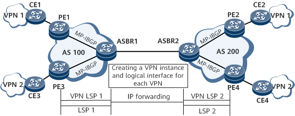
As a basic BGP/MPLS IP VPN application in the inter-AS scenario, Option A does not need special configurations and MPLS does not need to run between ASBRs. In this mode, ASBRs of two ASs directly connect to each other and function as PEs in the ASs. Each ASBR views the peer ASBR as its CE, creates a VPN instance for each VPN, and advertises IPv4 routes to the peer ASBR through EBGP.
On the network shown in Figure 1, for ASBR1 in AS 100, ASBR2 in AS 200 is a CE. Similarly, for ASBR2, ASBR1 is a CE. Here, a VPN LSP indicates a private network tunnel, and an LSP indicates a public network tunnel.
- Route advertisement in an inter-AS VPN Option A scenario
MP-IBGP runs between PEs and ASBRs to exchange VPN-IPv4 route information. A common PE-CE routing protocol (BGP or IGP multi-instance) or static route can be used between ASBRs for the exchange of VPN information. Because this involves interaction between different ASs, using EBGP is recommended.
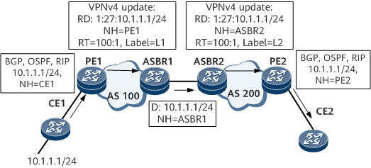
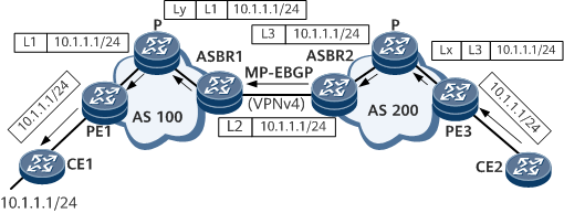
For example, CE1 advertises route 10.1.1.1/24 to CE2. Figure 2 shows the process. D indicates the destination address, NH the next hop, and L1 and L2 the VPN labels. This figure does not show the distribution of public network IGP routes and labels. - Packet forwarding in an inter-AS VPN Option A scenarioFigure 3 shows the process of forwarding packets through an LSP on the public network. L1 and L2 indicate VPN labels, and Lx and Ly public network labels.
Inter-AS VPN Option B
- Inter-AS VPN Option B overview
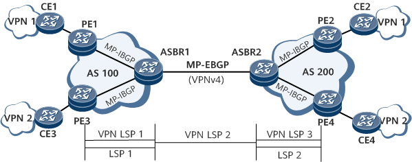
On the inter-AS VPN Option B network shown in Figure 4, two ASBRs use MP-EBGP to exchange labeled VPN-IPv4 routes received from local PEs in their respective ASs. A VPN LSP indicates a private network tunnel, and an LSP a public network tunnel.
In inter-AS VPN Option B, ASBRs receive all inter-AS VPN-IPv4 routes from the local and external ASs and then advertise these routes. In basic MPLS VPN implementation, a PE stores only the VPN routes that match the VPN targets of its local VPN instances. The ASBRs are configured to store all the received VPN routes, regardless of whether these routes match the VPN targets of its local VPN instances.
The advantage of this solution is that all traffic is forwarded by ASBRs. In this way, traffic is controllable, but the loads on the ASBRs are heavy. BGP routing policies, such as VPN target-based filtering policies, can be configured on ASBRs, so that ASBRs only save some of VPN-IPv4 routes.
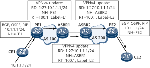
- Route advertisement in an inter-AS VPN Option B scenarioFigure 5 shows a route advertisement example. In this example, CE1 advertises route 10.1.1.1/24 to CE2. NH indicates the next hop, and L1, L2, and L3 the VPN labels. This figure does not show the distribution of public network IGP routes and labels. The specific process is as follows:
- CE1 uses BGP, OSPF, or RIP to advertise the route to PE1 in AS 100.
- PE1 in AS 100 uses MP-IBGP to advertise the labeled VPNv4 route to ASBR1 in AS 100. If a route reflector (RR) is deployed on the network, PE1 advertises the VPNv4 route to the RR, and the RR then reflects the route to ASBR1.
- ASBR1 uses MP-EBGP to advertise the labeled VPNv4 route to ASBR2. Because MP-EBGP changes the next hop of a route when advertising the route, ASBR1 allocates a new label to the VPNv4 route.
- ASBR2 uses MP-IBGP to advertise the labeled VPNv4 route to PE2 in AS 200. If an RR is deployed on the network, ASBR2 advertises the VPNv4 route to the RR, and the RR then reflects the route to PE2. When ASBR2 advertises routes to an MP-IBGP peer in the local AS, it changes the next hop of the routes to itself.
- PE2 in AS 200 uses BGP, OSPF, or RIP to advertise the route to CE2.
- Packet forwarding in an inter-AS VPN Option B scenario
In an inter-AS VPN Option B scenario, the two ASBRs need to swap VPN LSPs once during packet forwarding. Figure 6 shows the process of forwarding packets through an LSP on the public network. Here, L1, L2, and L3 indicate VPN labels, and Lx and Ly indicate public network labels (outer tunnel labels).
Inter-AS VPN Option C
- Inter-AS VPN Option C overview
In the preceding two inter-AS VPN modes, ASBRs need to maintain and distribute VPN-IPv4 routes. When each AS needs to exchange a large number of VPN routes, ASBRs may hinder network expansion.
One solution to the problem is that PEs directly exchange VPN-IPv4 routes with each other and ASBRs do not maintain or advertise such routes.
ASBRs use MP-IBGP to advertise labeled IPv4 routes to PEs in their respective ASs, and advertise labeled IPv4 routes received by PEs in their respective ASs to the peer ASBRs in other ASs. ASBRs in the intermediate AS also advertise labeled IPv4 routes. Therefore, a VPN LSP needs to be established between the ingress and egress PEs.
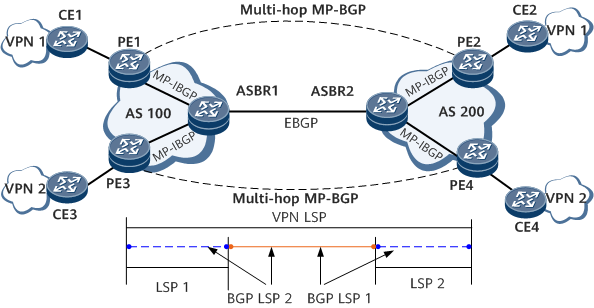
The PEs in different ASs establish multi-hop EBGP connections with each other to exchange VPN-IPv4 routes.
The ASBRs neither store VPN-IPv4 routes nor advertise VPN-IPv4 routes to each other.
Figure 7 shows the networking of inter-AS VPN Option C. In the figure, VPN LSPs are private network tunnels, and LSPs are public network tunnels. A BGP LSP enables two PEs to exchange loopback route information. A BGP LSP consists of two unidirectional BGP LSP. For example, BGP LSP1 is established from PE1 to PE2, and BGP LSP2 is established from PE2 to PE1.
To improve scalability, you can specify an RR in each AS. The RR stores all VPN-IPv4 routes and exchanges VPN-IPv4 routes with PEs in the same AS. The RRs in two ASs establish MP-EBGP connections with each other to advertise VPN-IPv4 routes.
Figure 8 Inter-AS VPN Option C with RRs deployed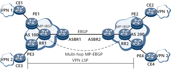
- Route advertisement in an inter-AS VPN Option C scenario
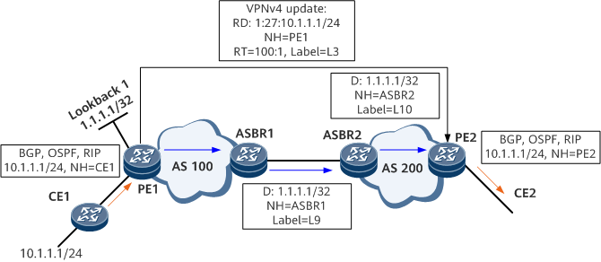
The key to implementing inter-AS VPN Option C is to establish inter-AS public network tunnels. For example, Figure 9 shows how CE1 advertises route 10.1.1.1/24. D indicates the destination address, NH the next hop, L3 the VPN label, and L9 and L10 the BGP LSP labels. This figure does not show the distribution of public network IGP routes and labels.
- Packet forwarding in an inter-AS VPN Option C scenario
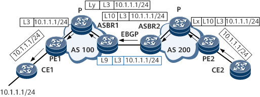
Figure 10 shows the process of forwarding packets through an LSP on the public network. L3 indicates the VPN label, L10 and L9 BGP LSP labels, and Lx and Ly public network labels (outer tunnel labels).
When PE2 forwards a packet to PE1, PE2 needs to add three labels to the packet: a VPN label, a BGP LSP label, and a public network label. When the packet reaches ASBR2, only the VPN label and BGP LSP label remain. After the packet reaches ASBR1, ASBR1 removes the BGP LSP label and forwards the packet as a common MPLS VPN packet.
Comparison of the Three Inter-AS VPN Modes
Inter-AS VPN |
Description |
|---|---|
Option A |
Easy configuration: MPLS is not required between ASBRs, and no special configuration is required for inter-AS connections. Poor scalability: ASBRs need to manage all VPN routes, and a VPN instance needs to be configured for each VPN. This results in numerous VPN-IPv4 routes on the ASBRs. In addition, because common IP forwarding is implemented between ASBRs, each inter-AS VPN requires a different interface, which can be a sub-interface, physical interface, or bundled logical interface. This poses high requirements for ASBRs. If a VPN spans multiple ASs, the intermediate ASs must support VPN services. This requires complex configurations and greatly affects the intermediate ASs. If only a few inter-AS VPN instances are used, Option A is recommended. |
Option B |
Unlike Option A, Option B is not restricted by the number of links between ASBRs. VPN route information is stored on and forwarded by ASBRs. If a large number of VPN routes exist, the overloaded ASBRs tend to become faulty points. Therefore, in scenarios where MP-EBGP is used, ASBRs that maintain VPN route information generally do not perform IP forwarding on the public network. |
Option C |
VPN routes are directly exchanged between the ingress and egress PEs. The routes do not need to be stored or forwarded by intermediate devices. Only PEs maintain VPN route information, and Ps and ASBRs are only responsible for packet forwarding. This means that the intermediate devices only need to support MPLS forwarding instead of MPLS VPN services. ASBRs are no longer bottlenecks. Option C, therefore, is suitable for VPNs spanning multiple ASs. MPLS VPN load balancing is easier to implement in Option C mode. The disadvantage of this mode is that it costs too much to manage an E2E BGP LSP between PEs. |
