IP FPM Basic Concepts
IP FPM Model
The IP Flow Performance Measurement (FPM) model describes how service flows are measured to obtain the packet loss rate and delay. In statistical terms, the statistical objects are the service flows, and statistical calculations determine the packet loss rate and delay of the service flows traveling across the transit network. Service flow statistical analysis is performed on the ingress and egress of the transit network.
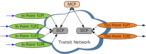
The IP FPM model is composed of three objects: target flows, a transit network, and the statistical system. The statistical system is further classified into the Target Logical Port (TLP), Data Collecting Point (DCP), and Measurement Control Point (MCP).Figure 1 shows the IP FPM model.
-
Target flows must be pre-defined.
One or more fields in IP headers can be specified to identify target flows. The field can be the source IP address or prefix, destination IP address or prefix, protocol type, source port number, destination port number, or type of service (ToS). The more fields specified, the more accurately flows can be identified. Specifying as many fields as possible is recommended to maximize measurement accuracy.
-
The transit network only bears target flows. The target flows are not generated or terminated on the transit network. The transit network can be a Layer 2 (L2), Layer 3 (L3), or L2+L3 hybrid network. Each node on the transit network must be reachable at the network layer.
-
TLPs are interfaces on the edge nodes of the transit network. TLPs perform the following actions:
- Compile statistics on the packet loss rate and delay.
- Generate statistics, such as the number of packets sent and received, traffic bandwidth, and timestamp.
An In-Point-TLP collects statistics about service flows it receives. An Out-Point-TLP collects statistics about service flows it sends.
-
DCPs are edge nodes on the transit network. DCPs perform the following actions:
- Manage and control TLPs.
- Collect statistics generated by TLPs.
- Report the statistics to an MCP.
-
MCPs can be any nodes on the transit network. MCPs perform the following actions:
- Collect statistics reported by DCPs.
- Summarize and calculate the statistics.
- Report measurement results to user terminals or the network management system (NMS).
Measurement Flags
Measurement flags, also called identification flags, identifies whether a specific packet is used to measure packet loss or delay.
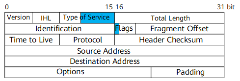
A specific bit in the IPv4 packet header can be specified as a measurement flag for packet loss or delay measurement.
The third to seventh bits in the ToS field are seldom used in actual applications. These bits, if available, can be used as measurement flags for service packets.
Bit 0 in the Flags field is reserved and can be used as a measurement flag.
If two or more bits in the IPv4 packet header have not been planned for other purposes, they can be used for packet loss and delay measurement at the same time. If only one bit in the IPv4 packet header has not been planned, it can be used for either packet loss or delay measurement in one IP FPM instance.