Basic Functions
Function Overview
IP Flow Performance Measurement (FPM) measures multipoint-to-multipoint (MP2MP) service flows to obtain the packet loss rate and delay.
Category |
Usage Scenario |
Function |
|
|---|---|---|---|
End-to-end performance statistics |
Proactive performance statistics |
When users want to detect network performance deterioration in real time, implement end-to-end proactive performance statistics to continuously monitor the network. |
|
On-demand performance statistics |
When network performance deteriorates or users want to learn real-time performance statistics of specific service flows, implement end-to-end on-demand performance statistics in a specified period. |
||
Hop-by-hop performance statistics |
On-demand performance statistics |
When network performance deteriorates, implement hop-by-hop on-demand performance statistics to locate a faulty node. |
|
Proactive performance statistics |
When network performance deteriorates, implement hop-by-hop proactive performance statistics to monitor the running status of each node, allowing users to detect network performance deterioration. |
||
Implementation
A bearer network has boundaries through which traffic enters and leaves. On the IP/MPLS network shown in Figure 1, PI(n) is the number of packets entering the network in the ingress direction on R(n), and PE(n) is the number of packets leaving the network in the egress direction on R(n).
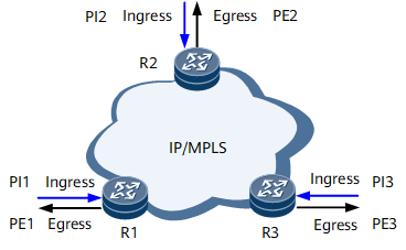
- The number of packets entering the network is the sum of all packets moving in the ingress direction: PI = PI(1) + PI(2) + PI(3)
- The number of packets leaving the network is the sum of all packets moving in the egress direction: PE = PE(1) + PE(2) + PE(3)
The difference between the time a service flow enters the network and the time the service flow leaves the network within a specified period is the delay.
Packet Loss Measurement
Packet loss measurement calculates the difference between the volume of traffic entering the network and the volume of traffic leaving the network over a specified period.
Figure 2 shows a typical network where end-to-end performance can be measured. Service packets enter the network from R1 and leave the network from R2.
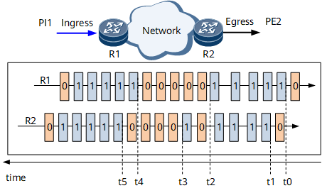
The parameters used in IP FPM packet loss measurement are as follows:
- t0: R1 sets the loss measurement flag to 1 for incoming service packets in the first period and starts counting all these service packets with the loss measurement flag of 1.
- t1: R2 starts receiving service packets with the loss measurement flag of 1 in the first period and starts counting these service packets.
- t2: R1 finishes counting the incoming service packets with the loss measurement flag of 1 in the first period and calculates the total number (PI1) of these service packets. R1 then sets the loss measurement flag to 0 for incoming service packets in the second period and starts counting all service packets with the loss measurement flag of 0.
- t3: R2 finishes receiving service packets with the loss measurement flag of 1 in the first period and calculates the total number (PE2) of these services packets.

R2 starts receiving service packets with the loss measurement flag as 1 from t1. At T3, the internal timer has run for a specified period. R2 determines that it finishes receiving service packets with the loss measurement flag as 1 in this period based on the period elapse, but not on whether service packets with the loss measurement flag as non-1 have been received. Therefore, service packet measurement will not be affected by packet disorder. This mechanism ensures that service packets in each period are correctly collected.
- t4: R1 sets the loss measurement flag to 1 for incoming service packets in the third period and starts counting all service packets with the loss measurement flag of 1.
- t5: R2 starts receiving service packets with the loss measurement flag of 1 in the third period and starts counting these service packets.
R2 can obtain the number of received service packets with the loss measurement flag of 1 in the first period any time between t3 and t5. The formula is LostPacket = PI1 - PE2.
If the peer end receives several copy traffic during the IP FPM measurement processing, the result of the IP FPM packet loss measurement may be inaccurate.
Delay Measurement
Delay measurement calculates the period from the time a service flow enters the network to the time the service flow leaves the network over a specified period.
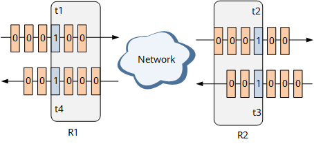
- When service packets are transmitted from R1 to R2, the procedure is as follows:
- t1: R1 sets the delay measurement flag to 1 for specified incoming service packets and obtains the timestamp t1.
- t2: R2 starts receiving the service packets with the delay measurement flag of 1 and obtains the timestamp t2.
- When service packets are transmitted from R2 to R1, the procedure is as follows:
- t3: R2 sets the delay measurement flag to 1 for specified incoming service packets and obtains the timestamp t3.
- t4: R1 starts receiving the service packets with the delay measurement flag of 1 and obtains the timestamp t4.
- The one-way delay from R1 to R2 is: 1d (R1 -> R2) = t2 - t1
- The one-way delay from R2 to R1 is: 1d (R2 -> R1) = t4 - t3
- The two-way delay is: 2d = (t2 - t1) + (t4 - t3) = (t4 - t1) - (t3 - t2)