Basic Concepts
Basic Design
STP runs at the data link layer. The devices running STP discover loops on the network by exchanging information with each other and trim the ring topology into a loop-free tree topology by blocking a certain interface. In this manner, replication and circular propagation of packets are prevented on the network. In addition, STP prevents the processing performance of devices from deteriorating.
Configuration BPDU: used to calculate a spanning tree and maintain the spanning tree topology.
Topology Change Notification (TCN) BPDU: used to inform associated devices of a topology change.

- Root bridge ID: is composed of a root bridge priority and the root bridge's MAC address. Each STP network has only one root bridge.
- Cost of the root path: indicates the cost of the shortest path to the root bridge.
- Designated bridge ID: is composed of a bridge priority and a MAC address.
- Designated port ID: is composed of a port priority and a port name.
- Message Age: specifies the lifetime of a BPDU on the network.
- Max Age: specifies the maximum time a BPDU is saved.
- Hello Time: specifies the interval at which BPDUs are sent.
- Forward Delay: specifies the time interface status transition takes.
One Root Bridge
A tree topology must have a root. Therefore, the root bridge is introduced by STP.
There is only one root bridge on the entire STP-enabled network. The root bridge is the logical center of but is not necessarily at the physical center of the entire network. The root bridge changes dynamically with the network topology.
After the network converges, the root bridge generates and sends out configuration BPDUs at specific intervals. Other devices forward the BPDUs, ensuring that the network topology is stable.
Two Types of Measurements
The spanning tree is calculated based on two types of measurements: ID and path cost.
-
Two types of IDs are available: Bridge IDs (BIDs) and Port IDs (PIDs).
-
As defined in IEEE 802.1D, a BID is composed of a 16-bit bridge priority and a bridge MAC address. The bridge priority occupies the left most 16 bits and the MAC address occupies the rightmost 48 bits.
On an STP-enabled network, the device with the smallest BID is selected to be the root bridge.
-
The PID is composed of a 4-bit port priority and a 12-bit port number. The port priority occupies the left most 4 bits and the port number occupies remaining bits on the right.
The PID is used to select the designated port.
The port priority affects the role of a port in a specified spanning tree instance. For details, see STP Topology Calculation.
-
-
The path cost is a port variable and is used to select a link. STP calculates the path cost to select a robust link and blocks redundant links to trim the network into a loop-free tree topology.
On an STP-enabled network, the accumulative cost of the path from a certain port to the root bridge is the sum of the costs of all the segment paths into which the path is separated by the ports on the transit bridges.
Table 1 shows the path costs defined in IEEE 802.1t. Different device manufacturers use different path cost standards.
Table 1 List of path costs Port Speed
Port Mode
STP Path Cost (Recommended Value)
802.1D-1998
802.1T
legacy
0
-
65535
200000000
200,000
10 Mbit/s
Half-Duplex
100
2000000
2,000
Full-Duplex
99
1999999
1,999
Aggregated Link 2 Ports
95
1000000
1800
Aggregated Link 3 Ports
95
666666
1600
Aggregated Link 4 Ports
95
500000
1400
100 Mbit/s
Half-Duplex
19
200000
200
Full-Duplex
18
199999
199
Aggregated Link 2 Ports
15
100000
180
Aggregated Link 3 Ports
15
66666
160
Aggregated Link 4 Ports
15
50000
140
1000 Mbit/s
Full-Duplex
4
20000
20
Aggregated Link 2 Ports
3
10000
18
Aggregated Link 3 Ports
3
6666
16
Aggregated Link 4 Ports
3
5000
14
10 Gbit/s
Full-Duplex
2
2000
2
Aggregated Link 2 Ports
1
1000
1
Aggregated Link 3 Ports
1
666
1
Aggregated Link 4 Ports
1
500
1
100Gbps
Full-Duplex
2
200
2
Aggregated Link 2 Ports
1
200
1
Aggregated Link 3 Ports
1
200
1
Aggregated Link 4 Ports
1
200
1
The rate of an aggregated link is the sum of the rates of all Up member links in the aggregated group.
Three Elements
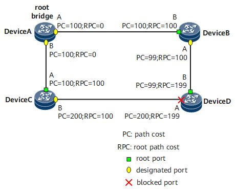
There are generally three elements used when a ring topology is to be trimmed into a tree topology: root bridge, root port, and designated port. Figure 1 shows the three elements.
-
The root bridge is the bridge with the smallest BID. The smallest BID is determined by exchanging configuration BPDUs.
-
The root port is a port that has the fewest path cost to the root bridge. To be specific, the root port is determined based on the path cost. Among all STP-enabled ports on a network bridge, the port with the smallest root path cost is the root port. There is only one root port on an STP-enabled device, but there is no root port on the root bridge.
-
For description of a designated bridge and designated port, see Table 2.
Table 2 Description of the designated bridge and designated port Object
Designated Bridge
Designated Port
Device
Device that forwards configuration BPDUs to a directly connected device
Designated bridge port that forwards configuration BPDUs to a device
LAN
Device that forwards configuration BPDUs to a network segment
Designated bridge port that forwards configuration BPDUs to a network segment.
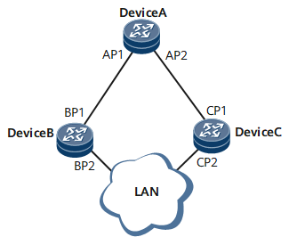
As shown in Figure 2, AP1 and AP2 reside on Device A; BP1 and BP2 reside on Device B; CP1 and CP2 reside on Device C.
Device A sends configuration BPDUs to Device B through AP1. Device A is the designated bridge of Device B, and AP1 on Device A is the designated port.
Two devices, Device B and Device C, are connected to the LAN. If Device B is responsible for forwarding configuration BPDUs to the LAN, Device B is the designated bridge of the LAN and BP2 on Device B is the designated port.
After the root bridge, root port, and designated port are selected successfully, the entire tree topology is set up. When the topology is stable, only the root port and the designated port forward traffic. All the other ports are in the Blocking state and receive only STP protocol packets instead of forwarding user traffic.
Four Comparison Principles
STP has four comparison principles that form a BPDU priority vector {root BID, total path costs, sender BID, port ID}.
Table 3 shows the information that is carried in the configuration BPDUs.
Field |
Brief Description |
|---|---|
Root BID |
Each STP-enabled network has only one root bridge. |
Root path cost |
Cost of the path from the port sending configuration BPDUs to the root bridge. |
Sender BID |
BID of the device sending configuration BPDUs. |
Port ID |
PID of the port sending configuration BPDUs. |
After a device on the STP-enabled network receives configuration BPDUs, it compares the fields shown in Table 3 with that of the configuration BPDUs. The four comparison principles are as follows:
During the STP calculation, the smaller the value, the higher the priority.
- Smallest BID: used to select the root bridge. Devices running STP select the smallest BID as the root BID shown in Table 3.
- Smallest root path cost: used to select the root port on a non-root bridge. On the root bridge, the path cost of each port is 0.
- Smallest sender BID: used to select the root port when a device running STP selects the root port between two ports that have the same path cost. The port with a smaller BID is selected as the root port in STP calculation. Assume that the BID of Device B is less than that of Device C in Figure 1. If the path costs in the BPDUs received by port A and port B on Device D are the same, port B becomes the root port.
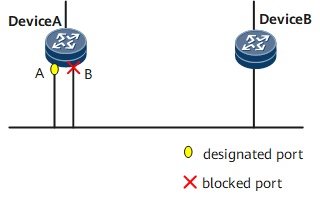
- Smallest PID: used to block the port with a greater PID but not the port with a smaller PID when the ports have the same path cost. The PIDs are compared in the scenario shown in Figure 3. The PID of port A on Device A is less than that of port B. In the BPDUs that are received on port A and port B, the path costs and BIDs of the sending devices are the same. Therefore, port B with a greater PID is blocked to cut off loops.
Port States
Table 4 shows the port status of an STP-enabled device.
Port State |
Purpose |
Description |
|---|---|---|
Forwarding |
A port in the Forwarding state forwards user traffic and BPDUs. |
Only the root port and designated port can enter the Forwarding state. |
Learning |
When a device has a port in the Learning state, the device creates a MAC address table based on the received user traffic but does not forward user traffic. |
This is a transitional state. |
Listening |
A port in the Listening state does not forward user traffic but receives BPDUs. |
A root port or designated port can enter the Listening state only when the alternate port, backup port, or protection function takes effect. |
Blocking |
A port in the Blocking state receives and forwards only BPDUs, not user traffic. |
This is the final state of a blocked port. |
Disabled |
A port in the Disabled state does not forward BPDUs or user traffic. |
The port is Down. |
Figure 4 shows the process of the state transition of a port.
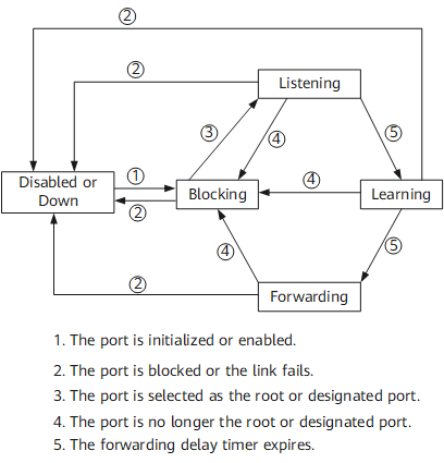

A Huawei datacom device uses MSTP by default. Port states supported by MSTP are the same as those supported by STP/RSTP.
The following parameters affect the STP-enabled port states and convergence.
Hello time
The Hello timer specifies the interval at which an STP-enabled device sends configuration BPDUs and Hello packets to detect link faults.
Modification of the Hello timer takes effect only if the configuration of the root bridge is modified. The root bridge adds certain fields in BPDUs to inform non-root bridges of the change in the interval. After a topology changes, TCN BPDUs will be sent. This interval is irrelevant to the transmission of TCN BPDUs.
Forward Delay time
The Forward Delay timer specifies the delay for interface status transition. When a link fault occurs, STP recalculation is performed, causing the structure of the spanning tree to change. The configuration BPDUs generated during STP recalculation cannot be immediately transmitted over the entire network. If the root port and designated port forward data immediately after being selected, transient loops may occur. Therefore, an interface status transition mechanism is introduced by STP. The newly selected root port and designated port do not forward data until an amount of time equal to twice the forward delay has past. In this manner, the newly generated BPDUs can be transmitted over the network before the newly selected root port and designated port forward data, which prevents transient loops.
The Forward Delay timer specifies the duration of a port spent in both the Listening and Learning states. The port in the Listening or Learning state is blocked, which is key to preventing transient loops.
Max Age time
The Max Age time specifies the aging time of BPDUs. The Max Age time can be manually configured on the root bridge.
Configuration BPDUs are transmitted over the entire network, ensuring a unique Max Age value. After a non-root bridge running STP receives a configuration BPDU, the non-root bridge compares the Message Age value with the Max Age value in the received configuration BPDU.- If the Message Age value is less than or equal to the Max Age value, the non-root bridge forwards the configuration BPDU.
- If the Message Age value is greater than the Max Age value, the configuration BPDU ages, and the non-root bridge directly discards it. In this case, the network size is considered too large and the non-root bridge disconnects from the root bridge.
If the configuration BPDU is sent from the root bridge, the value of Message Age is 0. Otherwise, the value of Message Age indicates the total time during which a BPDU is sent from the root bridge to the local bridge, including the delay in transmission. In real world situations, each time a configuration BPDU passes through a bridge, the value of Message Age increases by 1.