STP Topology Calculation
Initialization of the Spanning Tree
After all devices on the network are enabled with STP, each device considers itself the root bridge. Each device only transmits and receives Bridge Protocol Data Units (BPDUs) but does not forward user traffic. All ports are in the Listening state. After exchanging configuration BPDUs, all devices participate in the selection of the root bridge, root port, and designated port.
Root bridge selection
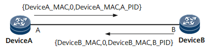
As shown in Figure 1, the quadruple marked with {} indicates a set of ordered vectors: root Bridge ID (BID) (DeviceA_MAC and DeviceB_MAC indicates the BIDs of two devices), total path costs, sender BID, and Port ID. Configuration BPDUs are sent at intervals set by the Hello timer. By default, the interval is 2 seconds.

As each bridge considers itself the root bridge, the value of the root BID field in the BPDU sent by each port is recorded as its BID; the value of the Root Path Cost field is the cumulative cost of all links to the root bridge; the sender BID is the ID of the local bridge; the Port ID is the Port ID (PID) of the local bridge port that sends the BPDU.
Once a port receives a BPDU with a priority higher than that of itself, the port extracts certain information from the BPDU and synchronizes its own information with the obtained information. The port stops sending the BPDU immediately after saving the updated BPDU.
When sending a BPDU, each device fills in the Sender BID field with its own BID. When a device considers itself the root bridge, the device fills in the Root BID field with its own BID. As shown in Figure 1, Port B on Device B receives a BPDU with a higher priority from Device A, and therefore considers Device A the root bridge. When another port on Device B sends a BPDU, the port fills in its Root BID field with DeviceA_BID. The preceding intercommunication is repeatedly performed between two devices until all devices consider the same device as the root bridge. This indicates that the root bridge is selected. Figure 2 shows the root bridge selection.
Root port selection
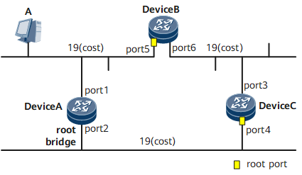
Each non-root bridge must and can only select one root port.
After the root bridge has been selected, each bridge determines the cost of each possible path from itself to the root bridge. From these paths, it picks one with the smallest cost (a least-cost path). The port connecting to that path becomes the root port of the bridge. Figure 3 shows the root port selection.
In the Root Path Cost algorithm, after a port receives a BPDU, the port extracts the value of the Root Path Cost field, and adds the obtained value and the path cost on the itself to obtain the root path cost. The path cost on the port covers only directly-connected path costs. The cost can be manually configured on a port. If the root path costs on two or more ports are the same, the port that sends a BPDU with the smallest sender BID value is selected as the root port.
Selection of a designated port
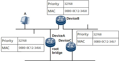
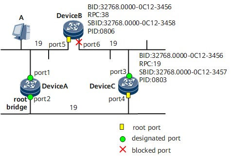
A port that discards lower-priority BPDUs received from other ports, whether on the local device or other devices on the network segment, is called a designated port on the network segment. As shown in Figure 1, assume that the MAC address of Device A is smaller than that of Device B. Port A on Device A is selected as a designated port. The device where a designated port resides is called a designated bridge on the network segment. In Figure 1, Device A is a designated bridge on the network segment.
After the network convergence is implemented, only the designated port and root port are in the Forwarding state. The other ports are in the Blocking state. They do not forward user traffic.
Ports on the root bridge are all designated ports unless loops occur on the root bridge. Figure 4 shows the designated port selection.
After the Topology Becomes Stable
After the topology becomes stable, the root bridge still sends configuration BPDUs at intervals set by the Hello timer. Each non-root bridge forwards the received configuration BPDUs by using its designated port. If the priority of the received BPDU is higher than that on the non-root bridge, the non-root bridge updates its own BPDU based on the information carried in the received BPDU.
STP Topology Changes
Figure 5 shows the packet transmission process after the STP topology changes.
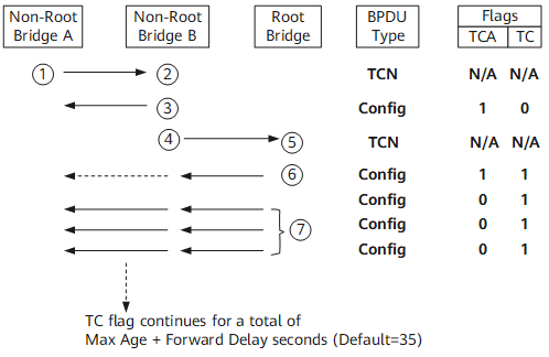
- After the network topology changes, a downstream device continuously sends Topology Change Notification (TCN) BPDUs to an upstream device.
- After the upstream device receives TCN BPDUs from the downstream device, only the designated port processes them. The other ports may receive TCN BPDUs but do not process them.
- The upstream device sets the TCA bit of the Flags field in the configuration BPDUs to 1 and returns the configuration BPDUs to instruct the downstream device to stop sending TCN BPDUs.
- The upstream device sends a copy of the TCN BPDUs to the root bridge.
- Steps 1, 2, 3, and 4 are repeated until the root bridge receives the TCN BPDUs.
- The root bridge sets the TC and TCA bits of the Flags field in the configuration BPDUs to 1 to instruct the downstream device to delete MAC address entries.
- TCN BPDUs are used to inform the upstream device and root bridge of topology changes.
- Configuration BPDUs with the Topology Change Acknowledgement (TCA) bit being set to 1 are used by the upstream device to inform the downstream device that the topology changes are known and instruct the downstream device to stop sending TCN BPDUs.
- Configuration BPDUs with the Topology Change (TC) bit being set to 1 are used by the upstream device to inform the downstream device of topology changes and instruct the downstream device to delete MAC address entries. In this manner, fast network convergence is achieved.
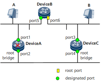
Figure 4 is used as an example to show how the network topology converges when the root bridge or designated port of the root bridge becomes faulty.
The root bridge becomes faulty.
As shown in Figure 6, the root bridge becomes faulty, Device B and Device C will reselect the root bridge. Device B and Device C exchange configuration BPDUs to select the root bridge.
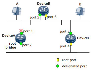
The designated port of the root bridge becomes faulty.
As shown in Figure 7, the designated port of the root bridge, port 1, becomes faulty. Port 6 is selected as the root port through exchanging configuration BPDUs of Device B and Device C.
In addition, port6 sends TCN BPDUs after entering the forwarding state. Once the root bridge receives the TCN BPDUs, it will send TC BPDUs to instruct the downstream device to delete MAC address entries.