VLAN Mapping
VLAN mapping, also called VLAN translation, converts between user VLAN IDs and ISP VLAN IDs.
VLAN mapping is implemented after packets are received on an inbound interface and before the packets are forwarded by an outbound interface.
After VLAN mapping is configured on an interface, the interface replaces the VLAN tag of a local VLAN frame with an external VLAN tag before sending the VLAN frame out.
When receiving the VLAN frame, the interface replaces the VLAN tag of a received VLAN frame with the local VLAN tag.
This implements inter-VLAN communication.
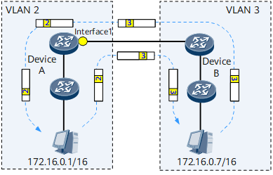
On the network shown in Figure 1, VLAN 2-VLAN 3 mapping is configured on Interface 1 of Switch A. Before Interface 1 sends a frame in VLAN 2 to VLAN 3, Interface 1 replaces VLAN ID 2 in the frame with VLAN ID 3 of VLAN 3. After Interface 1 receives a frame from VLAN 3, Interface 1 replaces VLAN ID 3 in the frame with VLAN ID 2 of VLAN 2. Therefore, devices in VLAN 2 and VLAN 3 can communicate.
If devices in two VLANs need to communicate using VLAN mapping, the IP addresses of these devices must be on the same network segment. Otherwise, devices in the two VLANs must communicate through routes, and VLAN mapping does not take effect.
The NetEngine 8000 F supports only 1 to 1 VLAN mapping. When a VLAN mapping-enabled interface receives a single-tagged frame, the interface replaces the VLAN ID in the frame with a specified VLAN ID.