VLAN Aggregation
Background
A VLAN is widely used on switching networks because of its flexible control of broadcast domains and convenient deployment. On a Layer 3 switch, the interconnection between the broadcast domains is implemented by using one VLAN with a logical Layer 3 interface. However, this wastes IP addresses.
Following is an example that shows how IP addresses are wasted.
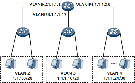
On the network shown in Table 1, VLAN 2 requires 10 host addresses. A subnet address 1.1.1.0/28 with a mask length of 28 bits is assigned to VLAN 2. 1.1.1.0 is the subnet number, and 1.1.1.15 is the directed broadcast address. These two addresses cannot serve as the host address. In addition, 1.1.1.1, as the default address of the network gateway of the subnet, cannot be used as the host address. The remaining 13 addresses ranging from 1.1.1.2 to 1.1.1.14 can be used by the hosts. In this way, although VLAN 2 needs only ten addresses, 13 addresses are assigned to it according to the subnet division.
VLAN 3 requires five host addresses. A subnet address 1.1.1.16/29 with a mask length of 29 bits is assigned to VLAN 3. VLAN 4 requires only one address. A subnet address 1.1.1.24/30 with a mask length of 30 bits is assigned to VLAN 4.
VLAN |
Subnet |
Gateway Address |
Number of Available Addresses |
Number of Available Hosts |
Practical Requirements |
|---|---|---|---|---|---|
2 |
1.1.1.0/28 |
1.1.1.1 |
14 |
13 |
10 |
3 |
1.1.1.16/29 |
1.1.1.17 |
6 |
5 |
5 |
4 |
1.1.1.24/30 |
1.1.1.25 |
2 |
1 |
1 |
The preceding VLANs require a total of 16 (10 + 5 + 1) addresses. However, at least 28 (16 + 8 4) addresses are occupied by the common VLANs. In this way, nearly half of the addresses are wasted. In addition, if only three hosts, not 10 hosts are bound to VLAN 2 later, the extra addresses cannot be used by other VLANs and thereby are wasted.
Meanwhile, this division is inconvenient for later network upgrades and expansions. For example, if you want to add two more hosts to VLAN 4 and do not want to change the IP addresses assigned to VLAN 4, and the addresses after 1.1.1.24 has been assigned to others, a new subnet with the mask length of 29 bits and a new VLAN must be assigned to the new hosts. VLAN 4 has only three hosts, but the three hosts are assigned to two subnets, and a new VLAN is required. This is inconvenient for network management.
In above, many IP addresses are used as the addresses of subnets, directional broadcast addresses of subnets, and default addresses of network gateways of subnets and therefore cannot be used as the host addresses in VLANs. This reduces addressing flexibility and wastes many addresses. To solve this problem, VLAN aggregation is used.
Principles
The VLAN aggregation technology, also known as the super VLAN, provides a mechanism that partitions the broadcast domain by using multiple VLANs in a physical network so that different VLANs can belong to the same subnet. In VLAN aggregation, two concepts are involved, namely, super VLAN and sub VLAN.
- Super VLAN: In a super VLAN that is different from a common VLAN, only Layer 3 interfaces are created, and physical ports are not contained. The super VLAN can be viewed as a logical Layer 3 concept. It is a collection of many sub VLANs.
- Sub VLAN: It is used to isolate broadcast domains. In a sub VLAN, only physical ports are contained, and Layer 3 VLAN interfaces cannot be created. A sub VLAN implements Layer 3 switching through the Layer 3 interface of the super VLAN.
A super VLAN can contain one or more sub VLANs that identify different broadcast domains. The sub VLAN does not occupy an independent subnet segment. In the same super VLAN, IP addresses of hosts belong to the subnet segment of the super VLAN, regardless of the mapping between hosts and sub VLANs.
Therefore, the same Layer 3 interface is shared by sub VLANs. Some subnet IDs, default gateway addresses of the subnet, and directed broadcast addresses of the subnet are saved; meanwhile, different broadcast domains can use the addresses in the same subnet segment. As a result, subnet differences are eliminated, addressing becomes flexible and idle addresses are reduced.
For example, on the network shown in Table 1, VLAN 2 requires 10 host addresses, VLAN 3 requires 5 host addresses, and VLAN 4 requires 1 host address.
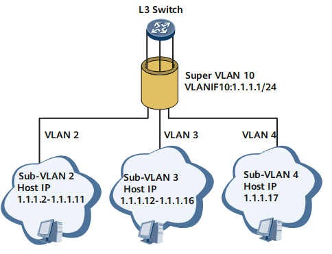
To implement VLAN aggregation, create VLAN 10 and configure VLAN 10 as a super VLAN. Then assign a subnet address 1.1.1.0/24 with the mask length of 24 to VLAN 10; 1.1.1.0 is the subnet number, and 1.1.1.1 is the gateway address of the subnet, as shown in Figure 2. Address assignment of sub VLANs (VLAN 2, VLAN 3, and VLAN 4) is shown in Table 2.
VLAN |
Subnet |
Gateway address |
Number of available addresses |
Available Addresses |
Practical requirements |
|---|---|---|---|---|---|
2 |
1.1.1.0/24 |
1.1.1.1 |
10 |
1.1.1.2-1.1.1.11 |
10 |
3 |
5 |
1.1.1.12-1.1.1.16 |
5 |
||
4 |
1 |
1.1.1.17 |
1 |
In VLAN aggregation implementation, sub VLANs are not divided according to the previous subnet border. Instead, their addresses are flexibly assigned in the subnet corresponding to the super VLAN according to the required host number.
As the Table 2 shows that VLAN 2, VLAN 3, and VLAN 4 share a subnet (1.1.1.0/24), a default gateway address of the subnet (1.1.1.1), and a directed broadcast address of the subnet (1.1.1.255). In this manner, the subnet ID (1.1.1.16, 1.1.1.24), the default gateway of the subnet (1.1.1.17, 1.1.1.25), and the directed broadcast address of the subnet (1.1.1.5, 1.1.1.23, and 1.1.1.24) can be used as IP addresses of hosts.
Totally, 16 addresses (10 + 5 + 1 = 16) are required for the three VLANs. In practice, in this subnet, a total of 16 addresses are assigned to the three VLANs (1.1.1.2 to 1.1.1.17). A total of 19 IP addresses are used, that is, the 16 host addresses together with the subnet ID (1.1.1.0), the default gateway of the subnet (1.1.1.1), and the directed broadcast address of the subnet (1.1.1.255). In the network segment, 236 addresses (255 - 19 = 236) are available, which can be used by any host in the sub VLAN.
Inter-VLAN Communication
Introduction
VLAN aggregation ensures that different VLANs use the IP addresses in the same subnet segment. This, however, leads to the problem of Layer 3 forwarding between sub VLANs.
In common VLAN mode, the hosts of different VLANs can communicate with each other based on the Layer 3 forwarding through their respective gateways. In VLAN aggregation mode, the hosts in a super VLAN use the IP addresses on the same network segment and share the same gateway address. The hosts in different sub VLANs belong to the same subnet. Therefore, they communicate with each other based on the Layer 2 forwarding, rather than the Layer 3 forwarding through a gateway. In practice, hosts in different sub VLANs are isolated in Layer 2. As a result, sub VLANs fail to communicate with each other.
To solve the preceding problem, you can use proxy ARP.

For details of proxy ARP, see the chapter "ARP" in the NetEngine 8000 F Feature Description - IP Services.
Layer 3 communication between different sub VLANs
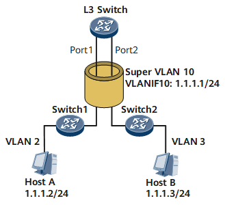
As shown in Figure 3, the super VLAN, VLAN 10, contains sub VLAN 2 and sub VLAN 3.
In the scenario where Host A has no ARP entry of Host B in its ARP table and the gateway (L3 Switch) has proxy ARP enabled, Host A in VLAN 2 wants to communication with Host B in VLAN 3. The communication process is as follows:
- After comparing the IP address of Host B 1.1.1.3 with its IP address, Host A finds that both IP addresses are on the same network segment 1.1.1.0/24 and its ARP table has no ARP entry of Host B.
- Host A broadcasts an ARP request to ask for the MAC address of Host B.
- Host B is not in the broadcast domain of VLAN 2, and cannot receive the ARP request.
- The proxy-ARP enabled gateway between the sub VLANs receives the ARP request from Host A and finds that the IP address of Host B 1.1.1.3 is the IP address of a directly connected interface. Then the gateway broadcasts an ARP request to all the other sub VLAN interfaces to ask for the MAC address of Host B.
- After receiving the ARP request, Host B sends an ARP response.
- After receiving the ARP response from Host B, the gateway replies with its MAC address to Host A.
- Both the gateway and Host A have the ARP entry of Host B.
- Host A sends packets to the gateway, and then the gateway sends the packets from Host A to Host B at the Layer 3. In this way, Host A and Host B can communicate with each other.
The process that Host B sends packets to Host A is similar, and is not mentioned.
Layer 2 communication between a sub VLAN and an external network
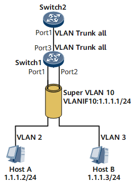
As shown in Figure 4, in the Layer 2 VLAN communications based on ports, the received or sent frames are not tagged with the super VLAN ID.
Host A sends a frame to Switch 1 through Port 1. Upon receipt, Switch 1 adds a VLAN tag with a VLAN ID 2 to the frame. The VLAN ID 2 is not changed to the VLAN 10 on Switch 1 even if VLAN 2 is the sub VLAN of VLAN 10. When the frame is sent by a trunk Port 3, it still carries the ID of VLAN 2.
That is to say, Switch 1 itself does not send the frames from VLAN 10. If Switch 1 receives frames from VLAN 10, it discards these frames as there is no physical port for VLAN 10.
A super VLAN has no physical port. This limitation is obligatory, as shown below:If you configure the super VLAN and then the trunk interface, the frames of a super VLAN are filtered automatically according to the allowed VLAN range set on the trunk interface.
On the network shown in Figure 4, no frame of super VLAN 10 passes through Port 3 on Switch 1, even though the interface allows frames from all VLANs to pass through.
If you configure the trunk interface and allow all VLAN packets to pass through, you still cannot configure the super VLAN on Switch 1, because any VLAN with physical ports cannot be configured as the super VLAN.
As for Switch 1, the valid VLANs are just VLAN 2 and VLAN 3, and all frames from these VLANs are forwarded.
Layer 3 communication between a sub VLAN and an external network
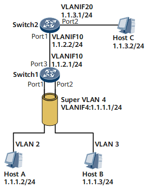
As shown in Figure 5, Switch 1 is configured with super VLAN 4, sub VLAN 2, sub VLAN 3, and a common VLAN 10. Switch 2 is configured with two common VLANs, namely, VLAN 10 and VLAN 20. Suppose that Switch 1 is configured with the route to the network segment 1.1.3.0/24, and Switch 2 is configured with the route to the network segment 1.1.1.0/24. Then Host A in sub VLAN 2 that belongs to the super VLAN 4 needs to communicate with Host C in Switch 2.- After comparing the IP address of Host C 1.1.3.2 with its IP address, Host A finds that two IP addresses are not on the same network segment 1.1.1.0/24.
- Host A broadcasts an ARP request to ask for the MAC address of the gateway (Switch 1).
- After receiving the ARP request, Switch 1 finds the ARP request packet is from sub VLAN 2 and replies with an ARP response to Host A through sub VLAN 2. The source MAC address in the ARP response packet is the MAC address of VLANIF 4 for super VLAN 4.
- Host A learns the MAC address of the gateway.
- Host A sends the packet to the gateway, with the destination MAC address as the MAC address of VLANIF 4 for super VLAN 4, and the destination IP address as 1.1.3.2.
- After receiving the packet, Switch 1 performs the Layer 3 forwarding and sends the packet to Switch 2, with the next hop address as 1.1.2.2, the outgoing interface as VLANIF 10.
- After receiving the packet, Switch 2 performs the Layer 3 forwarding and sends the packet to Host C through the directly connected interface VLANIF 20.
- The response packet from Host C reaches Switch 1 after the Layer 3 forwarding on Switch 2.
- After receiving the packet, Switch 1 performs the Layer 3 forwarding and sends the packet to Host A through the super VLAN.