E-Trunk
Definition
Enhanced Trunk (E-Trunk) implements inter-device link aggregation, providing device-level reliability.
Background
Eth-Trunk implements link reliability between single devices. However, if a device fails, Eth-Trunk fails to take effect.
To improve network reliability, carriers introduced device redundancy with master and backup devices. If the master device or primary link fails, the backup device can take over user services. In this situation, another device must be dual-homed to the master and backup devices, and inter-device link reliability must be ensured.
E-Trunk was introduced to meet the requirements. E-Trunk aggregates data links of multiple devices to form a link aggregation group (LAG). If a link or device fails, services are automatically switched to the other available links or devices in the E-Trunk, improving link and device-level reliability.
Basic Concepts
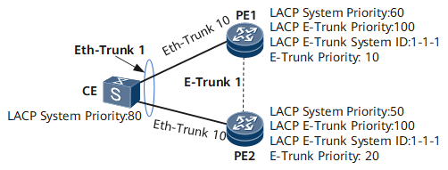
Basic E-Trunk concepts are introduced based on Figure 1.
The Link Aggregation Control Protocol (LACP) system priority of a member Eth-Trunk interface in an E-Trunk
For an Eth-Trunk interface that is a member interface of an E-Trunk, the LACP system priority is referred to as the LACP E-Trunk system priority.
When an E-Trunk consists of Eth-Trunk interfaces working in static LACP mode, each member Eth-Trunk interface and the connected peer Eth-Trunk interface use LACP E-Trunk system priorities to determine the priority of the device at either end of the Eth-Trunk link. The device with the higher priority functions as the LACP Actor and determines which member interfaces in its Eth-Trunk interface are active based on the interface priorities. The other device selects the member interfaces connected to the active member interfaces on the Actor as active member interfaces.
In an E-Trunk, to allow a CE to consider the peer PEs to be a single device, the peer PEs must have the same LACP E-Trunk system priority and system ID.

- The LACP E-Trunk system priority is used for the E-Trunk to which Eth-Trunk interfaces in static LACP mode are added.
- The LACP system priority is used for Eth-Trunk interfaces in static LACP mode.
On the network shown in Figure 1, the LACP system priorities of PE1 and PE2 are 60 and 50, respectively. The LACP E-Trunk system priorities of PE1 and PE2 are both 100. Because PE1 and PE2 are added to the E-Trunk, their LACP E-Trunk system priority 100 takes effect and is used when PE1 and PE2 perform LACP negotiation with the CE. Because the CE's LACP system priority is higher, the CE becomes the LACP Actor.
LACP system ID of a member Eth-Trunk interface in an E-Trunk
For an Eth-Trunk interface that is a member interface of an E-Trunk, the LACP system ID is referred to as the LACP E-Trunk system ID.
If two devices on an Eth-Trunk link have the same LACP E-Trunk system priority, the LACP E-Trunk system IDs are used to determine the devices' priorities. A smaller LACP E-Trunk system ID indicates a higher priority.
- The LACP E-Trunk system ID is used for the E-Trunk to which Eth-Trunk interfaces in static LACP mode are added.
- The LACP system ID is used for Eth-Trunk interfaces in static LACP mode.
E-Trunk priority
E-Trunk priorities determine the master/backup status of the devices in an aggregation group. As shown in Figure 1, the smaller the E-Trunk priority value, the higher the E-Trunk priority. PE1 has a higher E-Trunk priority than PE2, and therefore PE1 is the master device while PE2 is the backup device.
E-Trunk ID
An E-Trunk ID is an integer that uniquely identifies an E-Trunk.
Working mode
The working mode is subject to the working mode of the Eth-Trunk interface added to the E-Trunk. The Eth-Trunk interface works in one of the following modes: automatic, forced master and forced backup.- Automatic mode: Eth-Trunk interfaces as E-Trunk members work in automatic mode, and their master/backup status is determined through negotiation.
- Forced master mode: Eth-Trunk interfaces as E-Trunk members are forced to work in master mode.
- Forced backup mode: Eth-Trunk interfaces as E-Trunk members are forced to work in backup mode.
Timeout period
Normally, the master and backup devices in an E-Trunk periodically send Hello messages to each other. If the backup device does not receive any Hello message within the timeout period, it becomes the master device.
The timeout period is obtained through the formula: Timeout period = Sending period x Multiplier.
If the multiplier is 3, the backup device becomes the master device if it does not receive any Hello message within three consecutive sending periods.
How E-Trunk Works
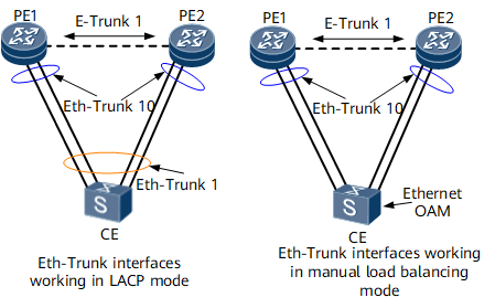
In Figure 2, the NetEngine 8000 F supports Eth-Trunk interfaces working in static LACP mode or manual load balancing mode to be added to an E-Trunk.
Eth-Trunk interfaces and E-Trunk deployment
PE end
The same Eth-Trunk and E-Trunk interfaces are created on PE1 and PE2. In addition, the Eth-Trunk interfaces are added to the E-Trunk group.
The Eth-Trunk interfaces can work in either static LACP mode or manual load balancing mode. The Eth-Trunk and E-Trunk configurations on PE1 and PE2 must be the same.
CE end
Adding Eth-Trunk interfaces in static LACP mode to an E-Trunk: Create an Eth-Trunk interface in static LACP mode on the CE, and add the CE interfaces connecting to the PEs to the Eth-Trunk interface. This ensures link reliability.
Adding Eth-Trunk interfaces in manual load balancing mode to an E-Trunk: Create an Eth-Trunk interface in manual load balancing mode on the CE, and add the CE interfaces connecting to the PEs to the Eth-Trunk interface. Then, configure Ethernet operation, administration and maintenance (OAM) on the CE and PEs, ensuring link reliability.
The E-Trunk group is invisible to the CE.
Eth-Trunk interfaces to be added to an E-Trunk can be either Layer 2 or Layer 3 interfaces.
When you configure IP addresses for Eth-Trunk interfaces connecting the CE and PEs to transmit Layer 3 services, the PE's Eth-Trunk interface configurations must meet the following requirements:The same IP address must be configured for the PE Eth-Trunk interfaces.
In most cases, the master device advertises the direct route to its Eth-Trunk interface, and the backup device does not. After a master/backup device switchover is complete, the new master device (former backup device) advertises the direct route to its Eth-Trunk interface.
The same MAC address must be configured for the PE Eth-Trunk interfaces.
This prevents the CE from updating its ARP entries for a long time when a master/backup device switchover is performed and therefore ensures uninterrupted service forwarding.
There are few scenarios for configuring IP addresses for Eth-Trunk interfaces, which connect the CE and PEs to transmit Layer 3 services and which on PEs are added to an E-Trunk. In most cases, Eth-Trunk interfaces work as Layer 2 interfaces.
- Sending and receiving E-Trunk packetsE-Trunk packets carrying the source IP address and port number configured on the local end are sent through UDP. Factors triggering the sending of E-Trunk packets are as follows:
The sending timer expires.
The configurations change. For example, the E-Trunk priority, packet sending period, timeout period multiplier, addition/deletion of a member Eth-Trunk interface, or source/destination IP address of the E-Trunk group changes.
A member Eth-Trunk interface fails or recovers.
E-Trunk master/backup status
PE1 and PE2 negotiate the E-Trunk master/backup status by exchanging E-Trunk packets. Normally, after the negotiation, one PE functions as the master and the other as the backup.
The master/backup status of a PE depends on the E-Trunk priority and E-Trunk ID carried in E-Trunk packets. The smaller the E-Trunk priority value, the higher the E-Trunk priority. The PE with the higher E-Trunk priority functions as the master. If the E-Trunk priorities of the PEs are the same, the PE with the smaller E-Trunk system ID functions as the master.
Master/backup status of a member Eth-Trunk interface in the E-Trunk
The master/backup status of a member Eth-Trunk interface in the local E-Trunk is determined by the master/backup status of the E-Trunk, the member Eth-Trunk interface's working mode, and the remote member Eth-Trunk interface's status.
As shown in Figure 2, PE1 and PE2 are on the two ends of an E-Trunk link. PE1 is considered as the local end and PE2 as the peer end.
Table 1 shows the status of each member Eth-Trunk interface in the E-Trunk group.
Table 1 Master/backup status of an E-Trunk and its member Eth-Trunk interfaces Status of the Local E-Trunk
Working Mode of the Local Eth-Trunk Interface
Status of the Peer Eth-Trunk Interface
Status of the Local Eth-Trunk Interface
-
Forced master
-
Master
-
Forced backup
-
Backup
Master
Automatic
Master
Backup
Master
Automatic
Backup
Master
Backup
Automatic
Backup
Master
Backup
Automatic
Master
Backup
In normal situations:
If PE1 functions as the master, Eth-Trunk 10 of PE1 functions as the master, and its link status is Up.
If PE2 functions as the backup, Eth-Trunk 10 of PE2 functions as the backup, and its link status is Down.
If the link between the CE and PE1 fails, the following situations occur:
PE1 sends an E-Trunk packet containing information about the faulty Eth-Trunk 10 of PE1 to PE2.
After receiving the E-Trunk packet, PE2 finds that Eth-Trunk 10 on the peer is faulty. Then, the status of Eth-Trunk 10 on PE2 becomes master. Through the LACP negotiation, the status of Eth-Trunk 10 on PE2 becomes Up.
The Eth-Trunk status on PE2 becomes Up, and traffic of the CE is forwarded through PE2. In this way, traffic destined for the peer CE is protected.
If PE1 is faulty, the following situations occur:
If the PEs are configured with BFD, the PE2 detects that the BFD session status becomes Down, then functions as the master and Eth-Trunk 10 of PE2 functions as the master.
If the PEs are not configured with BFD, PE2 will not receive any E-Trunk packet from PE1 before its timeout period runs out, after which PE2 will function as the master and Eth-Trunk 10 of PE2 will function as the master.
Through the LACP negotiation, the status of Eth-Trunk 10 on PE2 becomes Up. The traffic of the CE is forwarded through PE2. In this way, destined for the peer CE is protected.
BFD fast detection
A device cannot quickly detect a fault on its peer based on the timeout period of received packets. In this case, BFD can be configured on the device. The peer end needs to be configured with an IP address. After a BFD session is established to detect whether the route to the peer is reachable, the E-Trunk can sense any fault detected by BFD.
Switchback mechanism
The local device is in master state. In such a situation, if the physical status of the Eth-Trunk interface on the local device goes Down or the local device fails, the peer device becomes the master and the physical status of the member Eth-Trunk interface becomes Up.
When the local end recovers, the local end needs to function as the master. Therefore, the local Eth-Trunk interface enters the LACP negotiation state. After being informed by LACP that the negotiation ability is Up, the local device starts the switchback delay timer. After the switchback delay timer times out, the local Eth-Trunk interface becomes the master. After LACP negotiation, the Eth-Trunk interface becomes Up.
E-Trunk Restrictions
To improve the reliability of CE and PE links and to ensure that traffic can be automatically switched between these links, the configurations on both ends of the E-Trunk link must be consistent. Use the networking in Figure 2 as an example.
The Eth-Trunk link directly connecting PE1 to the CE and the Eth-Trunk link directly connecting PE2 to the CE must be configured with the same working rate, and duplex mode. This ensures that both Eth-Trunk interfaces have the same key and join the same E-Trunk group.
Peer IP addresses must be specified for the PEs to ensure Layer 3 connectivity. The address of the local PE is the peer address of the peer PE, and the address of the peer PE is the peer address of the local PE. Here, it is recommended that the addresses of the PEs are configured as loopback interface addresses.
The E-Trunk group must be bound to a BFD session.
The two PEs must be configured with the same security key (if necessary).