Link Aggregation Control Protocol
Emergence of Link Aggregation
With the wide application of Ethernet technology on metropolitan area networks (MANs) and wide area networks (WANs), carriers have an increasing requirement on the bandwidth and reliability of Ethernet backbone links. To obtain higher bandwidth, the conventional solution is to replace the existing interface boards with boards of higher capacity or install devices which support higher-capacity interface boards. However, this solution is costly and inflexible. To provide an economic and convenient solution, link aggregation is introduced. Link aggregation increases link bandwidth by bundling a group of physical interfaces into a single logical interface without the need to upgrade hardware. In addition, link aggregation can implement a link backup mechanism, which improves transmission reliability.
As a link aggregation technology, trunk bundles a group of physical interfaces into a logical interface to increase the bandwidth. However, trunk can only detect link disconnections, not link layer faults or link misconnections. The Link Aggregation Control Protocol (LACP) is therefore used to improve trunk fault tolerance, provide M:N backup for the trunk, and improve reliability.
LACP provides a standard negotiation mechanism for devices to automatically aggregate multiple links according to their configurations and enable the aggregated link to transmit and receive data. After an aggregated link is formed, LACP maintains the link status and implements dynamic link aggregation and deaggregation.
Basic Concepts
Link aggregation
Link aggregation is a method of bundling several physical interfaces into a logical interface to increase bandwidth and reliability.
Link aggregation group
A link aggregation group (LAG) or a trunk link is a logical link that aggregates several physical links.
If all these aggregated links are Ethernet links, the LAG is called an Ethernet link aggregation group, or an Eth-Trunk for short, and the interface at each end of the Eth-Trunk link is called an Eth-Trunk interface.
Each interface that is added to the Eth-Trunk interface is called a member interface.
An Eth-Trunk interface can be considered as a single Ethernet interface. The only difference lies that an Eth-Trunk interface needs to select one or more member Ethernet interfaces before forwarding data. You can configure features on an Eth-Trunk interface the same way as on a single Ethernet interface, except for some features that take effect only on physical Ethernet interfaces.

An Eth-Trunk member interface cannot be added to another Eth-Trunk interface.
Active and inactive interfaces
There are active and inactive interfaces in link aggregation. An interface that forwards data is active, while an interface that does not forward data is inactive.
A link connected to an active interface is an active link, while a link connected to an inactive interface is an inactive link.
To enhance link reliability, a backup link is used. Interfaces on the two ends of the backup link are inactive. The inactive interfaces become active only when the active interfaces fail.
Upper threshold for the number of active interfaces
In an Eth-Trunk interface, if an upper threshold for the number of active interfaces is configured and the number of available active interfaces exceeds the upper threshold, the number of active interfaces in the Eth-Trunk remains at the upper threshold value.
Lower threshold for the number of active interfaces
In an Eth-Trunk interface, if a lower threshold for the number of active interfaces is configured and the number of active interfaces falls below this threshold, the Eth-Trunk interface goes Down, and all member interfaces of the Eth-Trunk interface stop forwarding data. This prevents data loss during transmission when the number of active interfaces is insufficient.
The lower threshold configured for the number of active interfaces ensures the bandwidth of an Eth-Trunk link.
LACP system priority
An LACP system priority is set to prioritize the devices at both ends. A lower system LACP priority value indicates a higher LACP system priority. The device with a higher system priority is selected as the Actor, and then active member interfaces are selected according to the configuration of the Eth-Trunk interface on the Actor. In LACP mode, the active interfaces selected by devices must be consistent at both ends; otherwise, the LAG cannot be set up. To ensure the consistency of the active interfaces selected at both ends, you can set a higher priority for one end. Then the other end can select the active interfaces accordingly.
If neither of the devices at the two ends of an Eth-Trunk link is configured with the system priority, the devices adopt the default value 32768. In this case, the Actor is selected according to the system ID. That is, the device with the smaller system ID becomes the Actor.
LACP interface priority
An LACP interface priority is set to specify the priority of an interface to be selected as an active interface. Interfaces with higher priorities are selected as active interfaces.
A smaller LACP interface priority value indicates a higher LACP interface priority.
LACPDU sending mode
A member interface of an Eth-Trunk interface in static LACP mode can send LACPDUs in either active or passive mode:- In active mode, an interface sends LACPDUs to the peer end for negotiation immediately after being added to an Eth-Trunk interface in static LACP mode.
- In passive mode, an interface does not actively send LACPDUs after being added to an Eth-Trunk interface in static LACP mode. Instead, it responds to LACPDUs only when receiving LACPDUs from the peer end that works in active mode.
The Eth-Trunk member interfaces at both ends cannot both work in passive mode; otherwise, no ends actively send LACPDUs for negotiation, which means LACPDU negotiation fails.
M:N backup of member interfaces
Link aggregation in static LACP uses LACPDUs to negotiation on active link selection. This mode is also called M:N mode where M indicates the number of active links and N indicates the number of backup links. This mode improves link reliability and implements load balancing among the M active links.
On the network shown in Figure 1, M+N links with the same attributes (in the same LAG) are set up between two devices. When data is transmitted over the aggregation link, traffic is distributed among the active (M) links. No data is transmitted over the backup (N) links. Therefore, the actual bandwidth of the aggregation link is the sum of the bandwidth of the M links, and the maximum bandwidth that can be provided is the sum of the bandwidth of M + N links.
If one of the M links fails, LACP selects one available backup link from the N links to replace the faulty link. In this situation, the actual bandwidth of the aggregation link remains the sum of the bandwidth of M links, but the maximum bandwidth that can be provided is the sum of the bandwidth of M + N - 1 links.
M:N backup applies to the scenario where bandwidth of M links needs to be provided and link redundancy is required. If an active link fails, an LACP-enabled device can automatically select the backup link with the highest priority and add it to the LAG.
If no backup link is available and the number of Up member links is less than the lower threshold for the number of Up links, the device shuts down the trunk interface.
Link Aggregation Mode
Link aggregation can use manual load balancing or LACP:
Manual 1:1 master/backup mode
In 1:1 master/backup mode, an LAG contains only two member interfaces. One interface is the master interface and the other is the backup interface. In normal situations, only the master interface forwards traffic.
In manual mode, you must manually set up an Eth-Trunk and add an interface to the Eth-Trunk. You must also manually configure member interfaces to be in the active state.
The manual 1:1 master/backup mode is used when the peer device does not support LACP.
Manual load balancing mode
In this mode, you must manually create an Eth-Trunk interface and add member interfaces to it. The LACP protocol is not required.
All member interfaces forward data and perform load balancing.
In manual load balancing mode, traffic can be evenly distributed among all member interfaces. Alternatively, you can set different weights for member interfaces to implement uneven load balancing. The interfaces set with greater weights transmit more traffic.
If an active link of the LAG fails, traffic load balancing is implemented among the remaining active links.
LACP mode
In LACP mode, you also manually create a trunk interface and add member interfaces to it. Compared with link aggregation in manual load balancing mode, active interfaces in LACP mode are selected through the transmission of Link Aggregation Control Protocol Data Units (LACPDUs). This means that when a group of interfaces are added to a trunk interface, the status of each member interface (active or inactive) depends on the LACP negotiation.
Table 1 shows the similarities and differences between the manual load balancing mode and LACP mode.
Table 1 Comparison of manual load balancing and LACP mode Difference/Similarity
Manual Load Balancing Mode
LACP Mode
Difference
LACP is disabled.
Whether interfaces in an LAG can be aggregated is not checked.
LACP is enabled.
LACP checks whether interfaces in an LAG can be aggregated.
Here, aggregation means the bundling of all active interfaces.
Similarity
The LAG is created and deleted manually, and the member links are added and deleted manually.
Principle of Link Aggregation in Manual Load Balancing Mode
Link aggregation in manual load balancing mode is widely applied. In this mode, multiple interfaces can be manually added to an aggregation group, all of which forward data and participate in load balancing. This mode applies when a great amount of link bandwidth is required for two directly connected devices and one of them does not support LACP. As shown in Figure 2, Device A supports LACP, while Device B does not.
In this mode, load balancing is carried out among all member interfaces. The NetEngine 8000 F supports two types of load balancing:
Per-flow load balancing
Per-packet load balancing
Principle of Link Aggregation in LACP Mode
LACP, specified in IEEE 802.3 ad, provides a standardized means of exchanging information to dynamically configure and maintain link aggregation groups. The local device and the peer exchange information through LACPDUs.
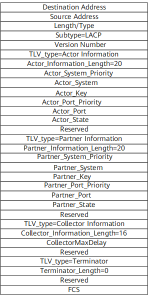
After member interfaces are added to a trunk interface, the member interfaces send LACPDUs to inform the peers of their system priorities, MAC addresses, interface priorities, interface numbers, and keys. After the peer receives the information, the peer compares this information with stored information and selects interfaces that can be aggregated. Devices at both ends then determine which interfaces are to be active interfaces.
Figure 3 shows the fields in an LACPDU.
An Eth-Trunk link in LACP mode is set up in the following process:
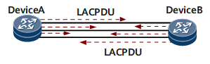
Devices at both ends send LACPDUs.
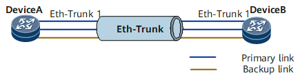
As shown in Figure 4, an Eth-Trunk interface in LACP mode is created on Device A and Device B, and member interfaces are added to each. Then LACP is automatically enabled on the member interfaces, and Device A and Device B send LACPDUs to each other.
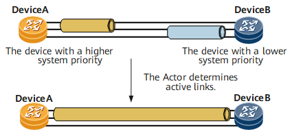
Devices at both ends determine the Actor according to the system LACP priority and system ID.
As shown in Figure 5, devices at both ends receive LACPDUs from each other. When Device B receives LACPDUs from Device A, Device B checks and records information about Device A and compares their system priorities. If the system priority of Device A is higher than that of Device B, Device A functions as the Actor and Device B selects active interfaces according to the interface priority of Device A. In this manner, devices on both ends select the same active interfaces.
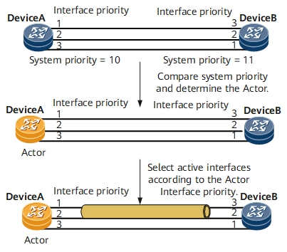
Devices at both ends determine active interfaces according to the LACP priorities and interface IDs of the Actor.
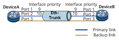
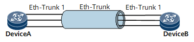
On the network shown in Figure 6, after the devices at both ends determine the Actor, both devices select active interfaces according to the interface priorities on the Actor.
Then active interfaces are selected, those to be included in the LAG are specified, and load balancing is implemented among these active links.
Switching between active links and inactive links
In LACP mode, if a device at either end detects any of the following events, link switching is triggered in the LAG.
A link is Down.
Ethernet OAM detects a link failure.
LACP discovers a link failure.
An active interface becomes unavailable.
After LACP preemption is enabled, the priority of the backup interface is changed to be higher than that of the current active interface.
If any of the preceding conditions are met, a link switching occurs in the following steps:
The faulty link is disabled.
The backup link with the highest priority is selected to replace the faulty active link.
The backup link of the highest priority becomes the active link and then begins forwarding data. The link switching is complete.
LACP preemption
After LACP preemption is enabled, interfaces with higher priorities in an LAG function as active interfaces.
As shown in Figure 7, Port 1, Port 2, and Port 3 are member interfaces of Eth-Trunk 1. The upper threshold for the number of active interfaces is 2. LACP priorities of Port 1 and Port 2 are set to 9 and 10, respectively. The LACP priority of Port 3 is the default value. When LACP negotiation is complete, Port 1 and Port 2 are selected as active interfaces because their LACP priorities are higher. Port 3 becomes the backup interface.
LACP preemption needs to be enabled in the following situations.
Port 1 fails and then recovers. When Port 1 fails, Port 3 takes its place. After Port 1 recovers, if LACP preemption is not enabled on Eth-Trunk 1, Port 1 remains as the backup interface. If LACP preemption is enabled on Eth-Trunk 1, Port 1 becomes the active interface after it recovers, and Port 3 becomes the backup interface again.
If LACP preemption is enabled and you want Port 3 to take the place of Port 1 or Port 2 as an active interface, you can set the LACP priority value of Port 3 to a smaller value. If LACP preemption is not enabled, the system does not re-select an active interface or switch the active interface when the priority of a backup interface is higher than that of the active interface.
LACP preemption delay
After LACP preemption occurs, the backup link waits for a period of time before switching to the Active state. This period of time is called an LACP preemption delay.
The LACP preemption delay can be set to prevent unstable data transmission on an Eth-Trunk link due to frequent link status changes.
As shown in Figure 6, Port 1 becomes an inactive interface due to a link fault. If the system is enabled with LACP preemption, Port 1 can resume its Active state only after a preemption delay when the link fault is rectified.
Loop detection
LACP supports loop detection. If a local Eth-Trunk interface in LACP mode receives a sole LACP protocol packet, the Eth-Trunk interface sets its member interfaces to the Unselected state so that they cease to participate in service traffic forwarding.
After the loop is eliminated:- If the Eth-Trunk interfaces on each end of a link can exchange LACPDUs normally and LACP negotiation succeeds, the member interfaces in Unselected state are restored to the Selected state and resume service traffic forwarding.
- If the Eth-Trunk interfaces on each end of a link still cannot exchange LACPDUs normally, the member interfaces remains in the Unselected state, and the member interfaces still cannot participate in service traffic forwarding.