BFD for PW
Service Overview
Bidirectional Forwarding Detection (BFD) for pseudo wire (PW) monitors PW connectivity on a Layer 2 virtual private network (L2VPN) and informs the L2VPN of any detected faults. Upon receiving a fault notification from BFD, the L2VPN performs a primary/secondary PW switchover to protect services.
BFD for PW has two modes: time to live (TTL) and non-TTL.
The two static BFD for PW modes are described as follows:
- Static BFD for PW in TTL mode: The TTL of BFD packets is automatically calculated or manually configured. BFD packets are encapsulated with PW labels and transmitted over PWs. A PW can either have the control word enabled or not. The usage scenarios of static BFD for PW in TTL mode are as follows:
Static BFD for single-segment PW (SS-PW): Two BFD-enabled nodes negotiate a BFD session based on the configured peer address and TTL (the TTL for SS-PWs is 1) and exchange BFD packets to monitor PW connectivity.
Static BFD for multi-segment PW (MS-PW): The remote peer address of the MS-PW to be detected must be specified. BFD packets can pass through multiple superstratum provider edge devices (SPEs) to reach the destination, regardless of whether the control word is enabled for the PW.
Static BFD for PW in non-TTL mode: The TTL of BFD packets is fixed at 255. BFD packets are encapsulated with PW labels and transmitted over PWs. A PW must have the control word enabled and differentiate control packets from data packets by checking whether these packets carry the control word.
Networking Description
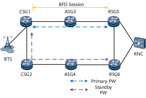
- Cell site gateway (CSG): CSGs form the access network. On the IP RAN, CSGs function as user-end provider edge devices (UPEs) to provide access services for NodeBs.
- Aggregation site gateway (ASG): On the IP RAN, ASGs function as SPEs to provide access services for UPEs.
- Radio service gateway (RSG): ASGs and RSGs form the aggregation network. On the IP RAN, RSGs function as network provider edge devices (NPEs) to connect to the radio network controller (RNC).
The primary PW is along CSG1–ASG3–RSG5 and the secondary PW is along CSG1–CSG2–ASG4-RSG6. If the primary PW fails, traffic switches to the secondary PW.
Feature Deployment
Configure static BFD for PW on the IP RAN as follows:
On CSG1, configure static BFD for the primary and secondary PWs.
On RSG5, configure static BFD for the primary PW.
On RSG6, configure static BFD for the secondary PW.

When you configure static BFD for PW, note the following points:
- When you configure static BFD for the primary PW, ensure that the local discriminator on CSG1 is the remote discriminator on RSG5 and that the remote discriminator on CSG1 is the local discriminator on RSG5.
- When you configure static BFD for the secondary PW, ensure that the local discriminator on CSG1 is the remote discriminator on RSG6 and that the remote discriminator on CSG1 is the local discriminator on RSG6.
After you configure static BFD for PW on CSG1 and primary/secondary RSGs, services can quickly switch to the secondary PW if the primary PW fails.