BFD for Multicast VPLS
Service Overview
IP/MPLS backbone networks carry an increasing number of multicast services, such as IPTV, video conferences, and massively multiplayer online role-playing games (MMORPGs), which all require bandwidth assurance, QoS guarantee, and high network reliability. To provide better multicast services, the IETF proposed the multicast VPLS solution. On a multicast VPLS network, the ingress transmits multicast traffic to multiple egresses over a P2MP MPLS tunnel. This solution eliminates the need to deploy PIM and HVPLS on the transit nodes, simplifying network deployment.
On a multicast VPLS network, multicast traffic can be carried over either P2MP TE tunnels or P2MP mLDP tunnels. When P2MP TE tunnels are used, P2MP TE FRR must be deployed. If a link fault occurs, FRR allows traffic to be rapidly switched to a normal link. If a node fails, however, traffic is not switched until the root node detects the fault and recalculates links to set up a Source to Leaf (S2L) sub-LSP. Topology convergence takes a long time in this situation, affecting service reliability.
To meet the reliability requirements of multicast services, configure BFD for multicast VPLS to monitor multicast VPLS links. When a link or node fails, BFD on the leaf nodes can rapidly detect the fault and trigger protection switching so that the leaf nodes receive traffic from the backup multicast tunnel.
Networking Description
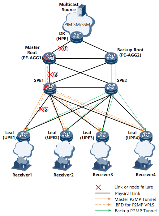
Figure 1 shows a dual-root 1+1 protection scenario in which PE-AGG1 is the master root node and PE-AGG2 is the backup root node. Each root node sets up a complete MPLS multicast tree to the UPEs (leaf nodes). The two MPLS multicast trees do not have overlapping paths. After multicast flows reach PE-AGG1 and PE-AGG2, PE-AGG1 and PE-AGG2 send the multicast flows along their respective P2MP tunnels to UPEs. Each UPE receives two copies of multicast flows and selects one to send to users.
- An IGP runs between the UPEs, SPEs, and PE-AGGs to implement Layer 3 reachability.
- Each PE-AGG sets up a P2P tunnel (a TE tunnel or LDP LSP) to each UPE. VPLS PWs are set up using BGP-AD. In addition, BGP-AD is used to set up P2MP LSPs from PE-AGG1 and PE-AGG2 to the UPEs. VPLS PWs recurse to the P2MP LSPs.
- A protection group is configured on each UPE for P2MP tunnels so that each UPE can select one from the two copies of multicast flows it receives.
- BFD for multicast VPLS is deployed for P2MP tunnels to implement protection switching when BFD detects a fault. On the PE-AGGs, BFD is configured to track the upstream AC interfaces. If the AC between NPE1 and PE-AGG1 fails, the UPEs receive multicast flows from NPE2.
BFD for multicast VPLS sessions are set up as follows:
- A root node triggers the establishment of a BFD session of the MultiPointHead type. Once established, the BFD session is initially Up and requires no negotiation. BFD triggers the root node to periodically send LSP ping packets along the P2MP tunnels and to send BFD detection packets at a configured BFD detection interval.
- A leaf node receives LSP ping packets and triggers the establishment
of a BFD session of the MultiPointTail type. Once established,
the BFD session is initially Down. After the leaf node receives BFD
detection packets indicating that the BFD session on the root node
is Up, the leaf node changes its BFD session to the Up state and starts
BFD detection.
 BFD for multicast VPLS sessions support only one-way detection. The BFD session of the MultiPointHead type on a root node only sends packets, whereas the BFD session of the MultiPointTail type on a leaf node only receives packets.
On the network shown in Figure 1, if link 1 (an AC) fails, BFD on the master root node detects that the AC interface is Down and stops sending BFD detection packets. The leaf nodes cannot receive BFD detection packets, and therefore report the Down event, which triggers protection switching. The leaf nodes then receive multicast flows from the backup multicast tunnel. Similarly, if node 2, link 3, node 4, or link 5 fails, the leaf nodes also receive multicast flows from the backup multicast tunnel. After the fault is rectified, BFD sessions are reestablished. The leaf nodes then receive multicast flows from the master multicast tunnel again.