IS-IS Routing Information Control
IS-IS routes calculated using the SPF algorithm may bring about some problems. For example, too many routing entries slow down route lookup, or link usage is unbalanced. As a result, IS-IS routing cannot meet carriers' network planning and traffic management requirements.
Route Leaking
When Level-1 and Level-2 areas both exist on an IS-IS network, Level-2 routers do not advertise the learned routing information about a Level-1 area and the backbone area to any other Level-1 area by default. Therefore, Level-1 routers do not know the routing information beyond the local area. As a result, the Level-1 routers cannot select the optimal routes to the destination beyond the local area.
With route leaking, Level-1-2 routers can select routes using routing policies, or tags and advertise the selected routes of other Level-1 areas and the backbone area to the Level-1 area. Figure 1 shows the typical networking for route leaking.
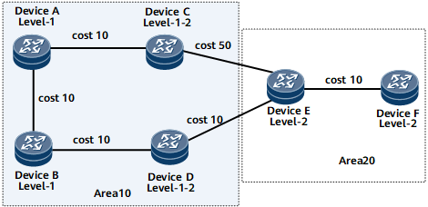
Device A, Device B, Device C, and Device D belong to area 10. Device A and Device B are Level-1 routers. Device C and Device D are Level-1-2 routers.
Device E and Device F belong to area 20 and are Level-2 routers.
If Device A sends a packet to Device F, the selected optimal route should be Device A -> Device B -> Device D -> Device E -> Device F because its cost is 40 (10 + 10 + 10 + 10 = 40) which is less than that of Device A -> Device C -> Device E -> Device F (10 + 50 + 10 = 70). However, if you check routes on Device A, you can find that the selected route is Device A -> Device C -> Device E -> Device F, which is not the optimal route from Device A to Device F.
This is because Device A does not know the routes beyond the local area, and therefore, the packets sent by Device A to other network segments are sent through the default route generated by the nearest Level-1-2 device.
In this case, you can enable route leaking on the Level-1-2 devices (Device C and Device D). Then, check the route and you can find that the selected route is Device A -> Device B -> Device D -> Device E -> Device F.
Route Summarization
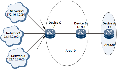
router A, router B, and router C use IS-IS to communicate with each other.
Device A belongs to area 20, and Device B and Device C belong to area 10.
Device A is a Level-2 router. Device B is a Level-1-2 router. Device C is a Level-1 router.
Device B maintains Level-1 and Level-2 LSDBs and leaks the routes to three network segments (172.16.1.0/24, 172.16.2.0/24, and 172.16.3.0/24) from the Level-1 area to the Level-2 area. If a link fault causes the Device C interface with IP address 172.16.1.1/24 to frequently alternate between Up and Down, the status change is advertised to the Level-2 area, triggering frequent LSP flooding and SPF calculation on Device A. As a result, the CPU usage on Device A increases, and even network flapping occurs.
On Device B, routes to the three network segments in the Level-1 area are summarized to one route to 172.16.0.0/22, which reduces the number of routing entries on Device B and minimizes the impact of route flapping in the Level-1 area on route convergence in the Level-2 area.
Load Balancing
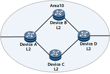
Device A, Device B, Device C, and Device D communicate with each other on an IP network using IS-IS.
Device A, Device B, Device C, and Device D belong to area 10 and are Level-2 routers.
If load balancing is not enabled, traffic on Device A is transmitted along the optimal route obtained using the SPF calculation. Consequently, traffic on different links is unbalanced. Enabling load balancing on Device A sends traffic to routerDevice D through routerDevice B and Device C. This transmission mode relieves the load on the optimal route.
Load balancing can work per-destination or per-packet. For details, see "Overview" in NetEngine 8000 F Feature Description - IP Routing.
In addition to the support for route balancing within the same process, IS-IS supports ECMP among several processes.
Administrative Tag
Administrative tags carry administrative information about IP address prefixes. When the cost type is wide, wide-compatible, or compatible and the prefix of the reachable IP address to be advertised by IS-IS has this cost type, IS-IS adds the administrative tag to the reachability type-length-value (TLV) in the prefix. In this manner, the administrative tag is advertised throughout the entire IS-IS area so that routes can be imported or filtered based on the administrative tag.
IS-IS Mesh Group
As defined in IS-IS, a router must flood the received LSP to all neighbors. On a network with multiple connections and point-to-point (P2P) links, this flooding method causes repeated LSP flooding and wastes bandwidth resources.
To address this issue, you can add certain interfaces to a mesh group. These interfaces flood the LSPs received from a group only to interfaces of other groups or interfaces on which no mesh groups are configured. All the interfaces that join a mesh group ensure the synchronization of the LSDBs in the entire network segment using the CSNP and PSNP mechanisms.
Link Group
In Figure 4, router A is dual-homed to the IS-IS network through router B and router C. The path router A -> router B is primary and the path router A -> router C is backup. The bandwidth of each link is 100 Gbit/s, and the traffic from Client is transmitted at 150 Gbit/s. In this situation, both links in the path router A -> router B or the path router A -> router C need to carry the traffic. If Link-a fails, Link-b takes over the traffic. However, traffic loss occurs because the bandwidth of Link-b is not sufficient enough to carry the traffic.
To address this problem, configure link groups. You can add multiple links to a link group. If one of the links fails and the bandwidth of all the links in the group is not sufficient enough to carry the traffic, the link group automatically increases the costs of the other links to a configured value so that this link group is not selected. Then, traffic is switched to another link group.
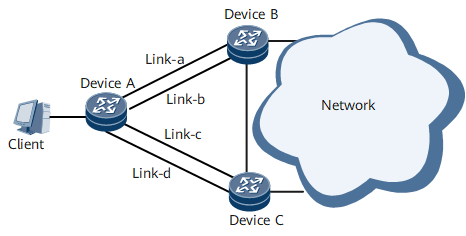
If Link-a fails, link group 1 automatically increases the cost of Link-b so that the traffic is switched to link group 2.
If both Link-a and Link-c fail, the link groups increase the costs of Link-b and Link-d (to the same value) so that Link-b and Link-d load-balance the traffic.