Basic Protocols of IS-IS
Related Concepts
DIS and Pseudo Node
A Designated Intermediate System (DIS) is an intermediate router elected in IS-IS communication. A pseudo node simulates a virtual node on a broadcast network and is not a real router. In IS-IS, a pseudo node is identified by the system ID and 1-byte circuit ID (a non-zero value) of a DIS.
The DIS is used to create and update pseudo nodes and generate the link state protocol data units (LSPs) of pseudo nodes. The routers advertise a single link to a pseudo node and obtain routing information about the entire network through the pseudo node. The router does not need to exchange packets with all the other routers on the network. Using the DIS and pseudo nodes simplifies network topology and reduces the length of LSPs generated by routers. When the network changes, fewer LSPs are generated. Therefore, fewer resources are consumed.
SPF Algorithm
The SPF algorithm, also named Dijkstra's algorithm, is used in a link-state routing protocol to calculate the shortest paths to other nodes on a network. In the SPF algorithm, a local router takes itself as the root and generates a shortest path tree (SPT) based on the network topology to calculate the shortest path to every destination node on a network. In IS-IS, the SPF algorithm runs separately in Level-1 and Level-2 databases.
Implementation
Establishment of IS-IS Neighbor Relationships
On different types of networks, the modes for establishing IS-IS neighbor relationships are different.
Establishment of a neighbor relationship on a broadcast link
Figure 1 Networking for a broadcast link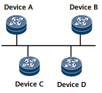
Device A, Device B, Device C, and Device D are Level-2 routers. Device A is newly added to the broadcast network. Figure 2 demonstrates the process of establishing the neighbor relationship between Device A and Device B, the process of establishing the neighbor relationship between Device A and Device C or Device D is similar to that between Device A and Device B.
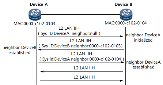
As shown in Figure 2, the process for establishing a neighbor relationship on a broadcast link consists of the following phases:- Device A broadcasts a Level-2 local area network (LAN) IS-to-IS Hello PDU (IIH). After Device B receives the IIH, Device B detects that the neighbor field in the IIH does not contain its media access control (MAC) address, and sets its neighbor status with Device A to Initial.
- Device B replies a Level-2 LAN IIH to Device A. After Device A receives the IIH, Device A detects that the neighbor field in the IIH contains its MAC address, and sets its neighbor status with Device B to Up.
- Device A sends a Level-2 LAN IIH to Device B. After Device B receives the IIH, Device B detects that the neighbor field in the IIH contains its MAC address, and sets its neighbor status with Device A to Up.
DIS Election
On a broadcast network, any two routers exchange information. If n routers are available on the network, n x (n - 1)/2 adjacencies must be established. Each status change of a router is transmitted to other routers, which wastes bandwidth resources. IS-IS resolves this problem by introducing the DIS. All routers send information to the DIS, which then broadcasts the network link status. Using the DIS and pseudo nodes simplifies network topology and reduces the length of LSPs generated by routers. When the network changes, fewer LSPs are generated. Therefore, fewer resources are consumed.
A DIS is elected after a neighbor relationship is established. Level-1 and Level-2 DISs are elected separately. You can configure different priorities for DISs at different levels. In DIS election, a Level-1 priority and a Level-2 priority are specified for every interface on every router. A router uses every interface to send IIHs and advertises its priorities in the IIHs to neighboring routers. The higher the priority, the higher the probability of being elected as the DIS. If there are multiple routers with the same highest priority on a broadcast network, the one with the largest MAC address is elected. The DISs at different levels can be the same router or different routers.
In the DIS election procedure, IS-IS is different from Open Shortest Path First (OSPF). In IS-IS, DIS election rules are as follows:- The router with the priority of 0 also takes part in the DIS election.
- When a new router that meets the requirements of being a DIS is added to the broadcast network, the router is selected as the new DIS, which triggers a new round of LSP flooding.
Establishment of a neighbor relationship on a P2P link
The establishment of a neighbor relationship on a P2P link is different from that on a broadcast link. A neighbor relationship on a P2P link can be established in 2-way or 3-way mode, as shown in Table 1. By default, the 3-way handshake mechanism is used to establish a neighbor relationship on a P2P link.Table 1 Comparison between 2-way mode and 3-way mode Mode Description Advantages and Disadvantages Reliability 2-way mode When a router receives an IIH, it unidirectionally sets up a neighbor relationship. Disadvantages: - The unstable link status causes the loss of complete sequence numbers protocol data units (CSNPs) that are sent once an adjacency is set up. As a result, the link state databases (LSDBs) of two neighboring routers are not synchronized during the LSP update period.
- If two or more links exist between two routers, an adjacency can still be set up when one link is Down and another is Up in the same direction. A router that fails to detect the faulty link may also forward packets over this link.
Low 3-way mode A neighbor relationship is established after IIHs are sent three times. Advantages: A neighbor relationship is established only when both ends are Up. This mechanism ensures that packets are transmitted securely. High
IS-IS is a link-state protocol. An IS-IS router obtains first-hand information from other routers running link-state protocols. Every router generates information about itself, directly connected networks, and links between itself and directly connected networks. The router then sends the generated information to other routers through adjacent routers. Every router saves link state information without modifying it. Finally, every router has the same network interworking information, and LSDB synchronization is complete. The process of synchronizing LSDBs is called LSP flooding. In LSP flooding, a router sends an LSP to its neighbors and the neighbors send the received LSP to their neighbors except the router that first sends the LSP. The LSP is flooded among the routers at the same level. This implementation allows each router at the same level to have the same LSP information and keep a synchronized LSDB.
Neighbor goes Up or Down.
related interface goes Up or Down.
Imported IP routes change.
Inter-area IP routes change.
A new metric value is configured for an interface.
Periodic updates occur.
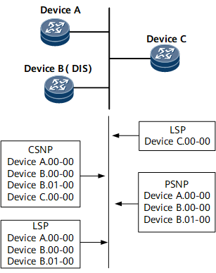
Updating the LSDB on a broadcast link
The DIS updates the LSDB to synchronize LSDBs on a broadcast network. Figure 3 shows the process of synchronizing LSDBs on a broadcast network.
When the DIS receives an LSP, it searches the LSDB for the related records. If the DIS does not find the LSP in its LSDB, it adds the LSP to its LSDB and broadcasts the new LSDB.
If the sequence number of the received LSP is greater than that of the local LSP, the DIS replaces the local LSP with the received LSP in the LSDB and broadcasts the new LSDB.
If the sequence number of the received LSP is less than that of the local LSP, the DIS sends the local LSP in the LSDB to the inbound interface.
If the sequence number of the received LSP is equal to that of the local LSP, the DIS compares the Remaining Lifetime of the two LSPs. If Remaining Lifetime of the received LSP is 0, the DIS replaces the LSP with the received LSP, and broadcasts the new LSDB. If the Remaining Lifetime of local LSP is 0, the DIS sends the LSP to the inbound interface.
If the sequence number of the received LSP and the local LSP in the LSDB are the same and neither Remaining Lifetime is 0, the DIS compares the checksum of the two LSPs. If the received LSP has a greater checksum than that of the local LSP in the LSDB, the DIS replaces the local LSP in the LSDB with the received LSP and advertises the new LSDB. If the received LSP has a smaller checksum than that of the local LSP in the LSDB, the DIS sends the local LSP in the LSDB to the inbound interface.
If the checksums of the received LSP and the local LSP are the same, the LSP is not forwarded.
Updating the LSDB on a P2P link
If the sequence number of the received LSP is greater than that of the local LSP in the LSDB, the router adds the received LSP to its LSDB. The router then sends a PSNP packet to acknowledge the received LSP and sends the LSP to all its neighbors except the neighbor that sends the LSP.
If the sequence number of the received LSP is less than that of the local LSP, the router directly sends its LSP to the neighbor and waits for a PSNP from the neighbor as an acknowledgement.
If the sequence number of the received LSP is the same as that of the local LSP in the LSDB, the router compares the Remaining Lifetimes of the two LSPs. If Remaining Lifetime of the received LSP is 0, the router adds the LSP to its LSDB. The router then sends a PSNP to acknowledge the received LSP. If Remaining Lifetime of the local LSP is 0, the router directly sends the local LSP to the neighbor and waits for a PSNP from the neighbor.
If the sequence number of the received LSP and the local LSP in the LSDB are the same, and neither Remaining Lifetime is 0, the router compares the checksum of the two LSPs. If the received LSP has a greater checksum than that of the local LSP, the router adds the received LSP to its LSDB. The router then sends a PSNP to acknowledge the received LSP. If the received LSP has a smaller checksum than that of the local LSP, the router directly sends the local LSP to the neighbor and waits for a PSNP from the neighbor. At last, the router sends the LSP to all its neighbors except the neighbor that sends the LSP.
If the checksums of the received LSP and the local LSP are the same, the LSP is not forwarded.
When LSDB synchronization is complete and network convergence is implemented, IS-IS performs SPF calculation by using LSDB information to obtain the SPT. IS-IS uses the SPT to create a forwarding database (a routing table).
In IS-IS, link costs are used to calculate shortest paths. The default cost for an interface on a Huawei router is 10. The cost is configurable. The cost of a route is the sum of the cost of every outbound interface along the route. There may be multiple routes to a destination, among which the route with the smallest cost is the optimal route.
Level-1 routers can also calculate the shortest path to Level-2 routers to implement inter-area route selection. When a Level-1-2 router is connected to other areas, the router sets the value of the attachment (ATT) bit in its LSP to 1 and sends the LSP to neighboring routers. In the route calculation process, a Level-1 router selects the nearest Level-1-2 router as an intermediate router between the Level-1 and Level-2 areas.