MPLS Ping/Tracert
Overview
The MPLS control plane establishes label switched paths (LSPs) but it cannot detect data forwarding failures in LSPs, which causes network maintenance difficulties. To address this issue, MPLS ping and tracert have been introduced to detect LSP errors and locate faulty nodes. MPLS ping is used to check link connectivity and host reachability on an MPLS network.
MPLS ping includes P2P MPLS ping and Point-to-Multipoint (P2MP) MPLS ping. In this document, MPLS ping refers to P2P MPLS ping unless otherwise specified.
Similar to a common ping or tracert mechanism, MPLS ping or MPLS tracert checks the LSP status by sending MPLS Echo Request and Reply messages. Both types of packets are UDP packets transmitted using UDP port 3503. The receive end uses the UDP port number to identify MPLS Echo Request and Reply messages.
An MPLS Echo Request message carries information about the forwarding equivalence class (FEC) for an LSP to be monitored. The MPLS Echo Request message is forwarded with other service packets of the same FEC along the LSP. This procedure enables the LSP connectivity to be monitored. In addition, Echo Request messages are transmitted to the destination using MPLS, whereas MPLS Echo Reply messages are transmitted to the source using IP.
To prevent the egress from forwarding a received MPLS Echo Request message to other nodes, set the destination address to 127.0.0.0/8 (the local loopback address) and the time to live (TTL) value to 1 in the IP header of the message.
MPLS Ping
MPLS ping process
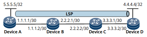
In Figure 1, an LSP destined for Device D is configured on Device A. The MPLS ping process on Device A is as follows:
Device A checks whether the LSP is established. If the LSP is a TE tunnel, Device A checks whether the tunnel interface is configured and the CR-LSP is established. If the LSP is not established, an error code is displayed, and the MPLS ping process ends. If the LSP has been established, the MPLS ping process continues.
Device A constructs an MPLS Echo Request message, with destination IP address 127.0.0.0/8 and TTL value 1 in the IP header. Then, Device A adds an LSP label to the MPLS Echo Request message and sends the message to Device B.
Transit nodes Device B and Device C forward this MPLS Echo Request message using MPLS.
If either transit node fails to forward the MPLS Echo Request message, this message is discarded.
If MPLS forwarding is successful, the MPLS Echo Request message reaches the egress Device D, and the Device D replies with an MPLS Echo Reply message to Device A.
MPLS Tracert
MPLS tracert process
In Figure 1, the MPLS tracert process of 4.4.4.4/32 on Device A is as follows:
Device A checks whether the LSP exists. If it does not exist, an error code is returned and the MPLS tracert process ends. If it exists, the MPLS tracert process continues.
Device A constructs an MPLS Echo Request message, with destination IP address 127.0.0.0/8 and TTL value 1 in the IP header. Then, Device A adds an LSP label (TTL value of the label is 1) to the MPLS Echo Request message and sends the message to Device B. Upon receipt, Device B determines that the TTL of the LSP label in the message has timed out so that it replies with an MPLS Echo Reply message. The message carries the destination UDP port equal to the source UDP port in the MPLS Echo Request message, and destination IP address equal to the source IP address of the MPLS Echo Request packet, and the TTL value of 255.
Upon receipt, Device A sends an MPLS Echo Request message with the TTL value of 2. Device B then forwards the message using MPLS. Upon receipt, Device C determines that the TTL of the LSP label in the message has timed out so that it replies with an MPLS Echo Reply message.
After receiving the MPLS Echo Reply message sent by Device C, Device A sends an MPLS Echo Request message with the TTL value of 3. Device C then forwards the packet using MPLS. Upon receipt, if Device D is the egress node, Device D replies with an MPLS Echo Reply message. Then Device A obtains information about all nodes on the path.
P2MP MPLS Ping
P2MP ping process
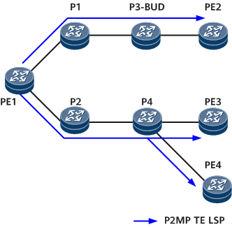
On the network shown in Figure 2, a P2MP TE LSP is established on PE1. PE2, PE3, PE4, and P3-BUD are leaf nodes. The P2MP ping process from PE1 on the LSP is as follows:
PE1 checks whether the LSP exists.
- If the LSP does not exist, an error code is displayed, and the P2MP Ping process ends.
- If the LSP exists, the P2MP ping process continues.
- PE1 constructs an MPLS Echo Request message, with destination IP address 127.0.0.0/8 and the TTL value of 1. Then PE1 adds an LSP label to the MPLS Echo Request message and sends the packet to P1 and P2 along the LSP.
- Transit nodes P1, P2 and P4 forward this MPLS Echo Request message using MPLS. P3, a bud node, forwards the MPLS Echo Request message and sends it to the CPU for processing. If either transit node fails to forward the MPLS Echo Request message, a node will send an MPLS Echo Reply message with an error code.
- After being forwarded successfully along the LSP, the MPLS Echo Request packet reaches the egresses: PE2, PE3, PE4, and P3-BUD. Each node replies with an MPLS Echo Reply message. Then PE1 obtains information about all nodes on the path.
SR-MPLS TE IPv4 Ping
- PE1 assigns the adjacency label 9001 to the PE1-P1 adjacency.
- P1 assigns the adjacency label 9002 to the P1-P2 adjacency.
- P2 assigns the adjacency label 9005 to the P2-PE2 adjacency.

- PE1 initiates a ping test and checks whether the specified tunnel is of the SR-MPLS TE type.
- If the tunnel type is not SR-MPLS TE, PE1 reports an error message indicating a tunnel type mismatch and stops the ping test.
- If the tunnel type is SR-MPLS TE, PE1 continues with the following operations.
- PE1 constructs an MPLS Echo Request packet encapsulating label information about the entire tunnel and carrying destination address 127.0.0.0/8 in the IP header of the packet.
- PE1 forwards the packet to P1. After receiving the packet, P1 removes the outer label 9002 and forwards the packet to P2.
- P2 removes the outer label 9005 of the received packet and forwards the packet to PE2 for processing.
- PE2 returns an MPLS Echo Reply packet to PE1.
SR-MPLS TE IPv4 Tracert
- PE1 initiates a tracert test and checks whether the specified tunnel is of the SR-MPLS TE type.
- If the tunnel type is not SR-MPLS TE, PE1 reports an error message indicating a tunnel type mismatch and stops the tracert test.
- If the tunnel type is SR-MPLS TE, PE1 continues with the following operations.
- PE1 constructs an MPLS Echo Request packet encapsulating label information about the entire tunnel and carrying destination address 127.0.0.0/8 in the IP header of the packet.
- PE1 forwards the packet to P1. After receiving the packet, P1 determines whether the TTL–1 value in the outer label of the packet is 0.
- If the TTL–1 value is 0, an MPLS TTL timeout occurs, and P1 sends the packet to the Rx/Tx module for processing.
- If the TTL–1 value is greater than 0, P1 removes the outer MPLS label of the packet, buffers the TTL–1 value, copies the value to the new outer MPLS label, searches the forwarding table for the outbound interface, and forwards the packet to P2.
- Similar to P1, P2 also determines whether the TTL–1 value in the outer label of the received packet is 0.
- If the TTL–1 value is 0, an MPLS TTL timeout occurs, and P2 sends the packet to the Rx/Tx module for processing.
- If the TTL–1 value is greater than 0, P2 removes the outer MPLS label of the packet, buffers the TTL–1 value, copies the value to the new outer MPLS label, searches the forwarding table for the outbound interface, and forwards the packet to PE2.
- P2 forwards the packet to PE2, and PE2 returns an MPLS Echo Reply packet to PE1.
SR-MPLS BE IPv4 Ping

- PE1 initiates a ping test and checks whether the specified tunnel is of the SR-MPLS BE IPv4 type.
- If the tunnel type is not SR-MPLS BE IPv4, PE1 reports an error message indicating a tunnel type mismatch and stops the ping test.
- If the tunnel type is SR-MPLS BE IPv4, PE1 continues with the following operations.
- PE1 constructs an MPLS Echo Request packet encapsulating the outer label of the initiator and carrying destination address 127.0.0.0/8 in the IP header of the packet.
- PE1 forwards the packet to P1. After receiving the packet, P1 swaps the outer MPLS label of the packet and forwards the packet to P2.
- Similar to P1, P2 swaps the outer MPLS label of the received packet and determines whether it is the penultimate hop. If yes, P2 removes the outer label and forwards the packet to PE2. PE2 sends the packet to the Rx/Tx module for processing.
- PE2 returns an MPLS Echo Reply packet to PE1 and generates the ping test result.
SR-MPLS BE IPv4 Tracert
- PE1 initiates a tracert test and checks whether the specified tunnel is of the SR-MPLS BE IPv4 type.
- If the tunnel type is not SR-MPLS BE IPv4, PE1 reports an error message indicating a tunnel type mismatch and stops the tracert test.
- If the tunnel type is SR-MPLS BE IPv4, PE1 continues with the following operations.
- PE1 constructs an MPLS Echo Request packet encapsulating the outer label of the initiator and carrying destination address 127.0.0.0/8 in the IP header of the packet.
- PE1 forwards the packet to P1. After receiving the packet, P1 determines whether the TTL–1 value in the outer label of the packet is 0.
- If the TTL–1 value is 0, an MPLS TTL timeout occurs, and P1 sends the packet to the Rx/Tx module for processing.
- If the TTL–1 value is greater than 0, P1 swaps the outer MPLS label of the packet, searches the forwarding table for the outbound interface, and forwards the packet to P2.
- Similar to P1, P2 also performs the following operations:
- If the TTL–1 value is 0, an MPLS TTL timeout occurs, and P2 sends the packet to the Rx/Tx module for processing.
- If the TTL–1 value is greater than 0, P2 swaps the outer MPLS label of the received packet and determines whether it is the penultimate hop. If yes, P2 removes the outer label, searches the forwarding table for the outbound interface, and forwards the packet to PE2.
- PE2 sends the packet to the Rx/Tx module for processing, returns an MPLS Echo Reply packet to PE1, and generates the tracert test result.