PW Ping/Tracert
Overview
The pseudowire (PW) ping and tracert operations use MPLS Echo Request and Reply messages to check whether a label switched path (LSP) is available. The MPLS Echo messages use port number 3503, and the network identifies them by this port number.
An MPLS Echo Request message carries the forwarding equivalence class (FEC) code. The network sends all packets with the same FEC code along the same LSP to detect the connectivity of the LSP. An MPLS network sends MPLS Echo Request messages to remote devices, whereas an IP network forwards MPLS Echo Reply messages to local devices.
To prevent the egress from forwarding MPLS Echo Request messages to other nodes when they arrive, the ingress sets the destination address in the IP header of the messages to 127.0.0.1/8, which is the loopback interface address of a local device. The ingress also sets the TTL field value in the IP header to 1.
The following PW ping/tracert operations are supported:
- VPWS PW Ping/Tracert
- VPLS PW Ping/Tracert
VPWS PW Ping/Tracert
VPWS PW ping/tracert monitors single-segment PW (SS-PW) and multi-segment PW (MS-PW) connectivity.
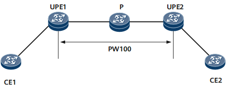
On the network shown in Figure 1, UPE1 performs a VPWS SS-PW ping operation.
- UPE1 checks whether PW100 exists. If PW100 does not exist, UPE1 generates an error message and terminates the ping operation. If PW100 exists, UPE1 performs the following operations.
- UPE1 constructs an MPLS Echo Request message, in which the destination IP address is 127.0.0.1/8 and the IP TTL value is 1 in the IP header. UPE1 searches for a corresponding LSP, encapsulates the LSP label into the MPLS Echo Request message, and sends the message to the P node.
- The P node forwards the MPLS Echo Request message to UPE2.
- If the MPLS LSP is functioning correctly, the MPLS Echo Request message arrives at the egress UPE2. UPE2 then sends an MPLS Echo Reply message to UPE1.
On the network shown in Figure 1, UPE1 performs a VPWS SS-PW ping tracert:
- UPE1 checks whether PW100 exists. If PW100 does not exist, UPE1 generates an error message and terminates the tracert operation. If PW100 exists, UPE1 performs the following operations.
- UPE1 constructs an MPLS Echo Request message, in which the destination IP address is 127.0.0.1/8 and the IP TTL value is 1 in the IP header. UPE1 searches for a corresponding LSP, encapsulates the LSP label into the MPLS Echo Request message, and sends the message to the P node.
- The P node receives the MPLS Echo Request message and then returns an MPLS Echo Reply message to UPE1 when the TTL in the LSP label times out. In the MPLS Echo Reply message, the destination UDP port number and destination IP address are respectively the source UDP port number and source IP address in the MPLS Echo Request message, and the IP TTL value is 255.
- Upon receipt, UPE1 sends another MPLS Echo Request message in which the IP TTL value is 2. The P node forwards the MPLS Echo Request message to UPE2 using MPLS. Upon receipt, UPE2 determines itself to be the egress and then sends an MPLS Echo Reply message to UPE1.
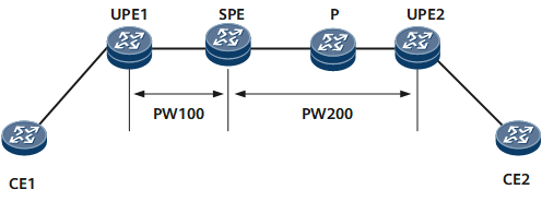
On the network shown in Figure 2, UPE1 performs a VPWS MS-PW ping operation.
- UPE1 checks whether PW100 exists. If PW100 does not exist, UPE1 generates an error message and terminates the ping operation. If PW100 exists, UPE1 performs the following operations.
- UPE1 constructs an MPLS Echo Request message, in which the destination IP address is 127.0.0.1/8 and the IP TTL value is 1 in the IP header. UPE1 searches for an LSP, encapsulates the LSP label into the MPLS Echo Request message, and sends the packet to the SPE.
- If the TTL in the LSP label has not expired (the TTL value is not 0), the SPE forwards the MPLS Echo Request message to UPE2 instead of sending the packet to the CPU.
- The MPLS Echo Request message then passes through the P node to reach the egress UPE2 on the LSP. UPE2 then sends an MPLS Echo Reply message to UPE1.
On the network shown in Figure 2, UPE1 performs a VPWS MS-PW tracert operation:
- UPE1 checks whether PW100 exists. If PW100 does not exist, UPE1 generates an error message and terminates the tracert operation. If PW100 exists, UPE1 performs the following operations.
- UPE1 constructs an MPLS Echo Request message, in which the destination IP address is 127.0.0.1/8 and the IP TTL value is 1 in the IP header. UPE1 searches for an LSP, encapsulates the LSP label into the MPLS Echo Request message, and sends the packet to the SPE.
- The SPE receives the MPLS Echo Request message and then returns an MPLS Echo Reply message to UPE1 when the TTL in the LSP label times out. In the MPLS Echo Reply message, the destination UDP port number and destination IP address are respectively the source UDP port number and source IP address in the MPLS Echo Request message, and the IP TTL value is 255.
- Upon receipt, UPE1 sends another MPLS Echo Request message in which the IP TTL value is 2. The SPE forwards the MPLS Echo Request message to the P node. The P node receives the MPLS Echo Request message and then returns an MPLS Echo Reply message to UPE1 when the TTL in the LSP label times out.
- Upon receipt, UPE1 sends another MPLS Echo Request message in which the IP TTL value is 3. The SPE forwards the MPLS Echo Request message to UPE2. Upon receipt, UPE2 determines itself to be the egress and then sends an MPLS Echo Reply message to UPE1.
VPWS PW ping/tracert can use the control-word, label-alert, or TTL detection mode to enable the destination (UPE2) to forward received packets to the CPU for processing instead of forwarding them to other devices.
Detection Mode |
Usage Scenario |
Description |
|---|---|---|
Control-word |
Supports SS-PW and MS-PW detection. |
|
Label-alert |
Supports only SS-PW detection. |
|
TTL |
Supports SS-PW and MS-PW detection. |
Specifies the expiration value. You must specify a TTL value to ensure that the TTL expires on the destination device so that the device sends the packet to the CPU for processing. |
VPLS PW Ping/Tracert
VPLS PW ping/tracert only supports the label-alert mode. This mode ensures that the network sends packets that the destination device receives to the CPU for processing instead of forwarding them to other devices.
Figure 3 illustrates the VPLS PW ping/tracert networks.
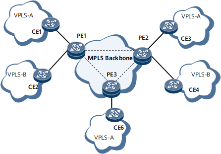
The VPLS PW ping process is as follows:
- An ingress searches for a PW using the virtual switching instance (VSI) name, peer IP, and PW ID. If the PW does not exist, the ingress generates an error message and terminates the ping operation.
- The ingress constructs an MPLS Echo Request message in which the destination address is 127.0.0.1/8 and the IP TTL value is 1 in the IP header. The ingress searches for a corresponding LSP, encapsulates an LSP label into the message, and sends the message.
- The network sends the MPLS Echo Request message along the LSP. When the MPLS Echo Request message reaches the egress, the egress then sends an MPLS Echo Reply message to the ingress.
The VPLS PW tracert process is as follows:
- An ingress searches for a PW using the VSI name, peer IP, and PW ID. If the PW does not exist, the ingress generates an error message and terminates the tracert operation.
- The ingress constructs an MPLS Echo Request message, in which the destination IP address is 127.0.0.1/8 and the IP TTL value is 1 in the IP header. The ingress searches for a corresponding LSP, encapsulates an LSP label into the message, and sends the message.
- The network sends the MPLS Echo Request message along the LSP. When the MPLS Echo Request message reaches the egress, the egress sends an MPLS Echo Reply message to the ingress.
- Upon receipt, the ingress determines that the MPLS Echo Request message has reached the egress and then terminates the tracert operation.