EVPN VPWS Ping/Tracert
Overview
The EVPN VPWS control plane establishes label switched paths (LSPs) but it cannot detect data forwarding failures in LSPs, which causes network maintenance difficulties. To address this issue, EVPN VPWS ping/tracert has been introduced to detect EVPN VPWS tunnel errors and locate failure nodes.
Similar to MPLS ping, EVPN VPWS ping uses EVPN VPWS Echo Request and EVPN VPWS Echo Reply messages to detect EVPN VPWS connectivity. The two messages are sent in UDP packets with port number 3503. The receive end identifies EVPN VPWS Echo Request and EVPN VPWS Echo Reply messages based on the UDP port number.
An EVPN VPWS echo request message carries information about the forwarding equivalence class (FEC) for an EVPN VPWS tunnel to be monitored. The EVPN VPWS echo request message is forwarded with other service packets of the same FEC along the EVPN VPWS tunnel. This procedure enables EVPN VPWS connectivity check. In addition, EVPN VPWS echo request messages are transmitted to the destination using EVPN VPWS tunnels, whereas EVPN VPWS echo reply messages are transmitted to the source using IP.

Currently, EVPN VPWS ping/tracert supports EVPN VPWS public network tunnels including LDP, TE, BGP LSP,SRv6 BE, SRv6 TE Policy, SR-MPLS TE, and SR-MPLS BE tunnels. In EVPN VPWS Tracert for BGP LSP scenarios, the label address family is not supported.
EVPN VPWS Ping in a Single-Active Scenario
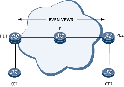
In Figure 1, CE1 and CE2 are user access devices directly connected to the MPLS network. The process of initiating an EVPN VPWS ping test from PE1 is as follows:
PE1 initiates a test to check whether the tunnel between a specified source EVPN VPWS ID and a specified destination EVPN VPWS ID exists.
- If the tunnel does not exist, PE1 reports an error message indicating that the tunnel does not exist and stops the ping test.
- If the tunnel exists, PE1 continues the ping operation.
PE1 uses the source EVPN VPWS ID and destination EVPN VPWS ID to subscribe to VPWS tunnel information, and constructs an MPLS echo request packet encapsulating the outer label of the initiator and carrying destination address 127.0.0.0/8 in the IP header of the packet, and sends the packet to the P.
P swaps the outer MPLS label of the received packet and determines whether it is the penultimate hop. If yes, P removes the outer label and forwards the packet to PE2. PE2 sends the packet to the Rx/Tx module for processing.
PE2 returns an MPLS echo reply packet to PE1 and generates the ping test result.
EVPN VPWS Tracert in a Single-Active Scenario
Figure 1 shows the process of initiating an EVPN VPWS tracert test from PE1.
PE1 initiates a test to check whether the tunnel between a specified source EVPN VPWS ID and a specified destination EVPN VPWS ID exists.
- If the tunnel does not exist, PE1 reports an error message indicating that the tunnel does not exist and stops the tracert test.
- If the tunnel exists, PE1 continues the tracert operation.
PE1 uses the source EVPN VPWS ID and destination EVPN VPWS ID to subscribe to VPWS tunnel information and next-hop information based on the tunnel type, constructs an MPLS echo request packet encapsulating label information about the entire tunnel and carrying destination address 127.0.0.0/8 in the IP header of the packet, and sends the packet to the P.
- After receiving the MPLS echo request packet, P determines whether the TTL–1 value in the outer label of the received packet is 0.
If the TTL-1 value is 0, an MPLS TTL timeout occurs. P sends the packet to the Rx/Tx module for processing.
If the TTL-1 value is greater than 0, P swaps the outer MPLS label of the packet, searches the forwarding table for the outbound interface, and forwards the packet to PE2.
- After receiving the packet, PE2 sends it to the Rx/Tx module for processing, returns an MPLS echo reply packet to PE1, and generates the tracert test result.
EVPN VPWS Ping in an Inter-AS Active-Active Scenario
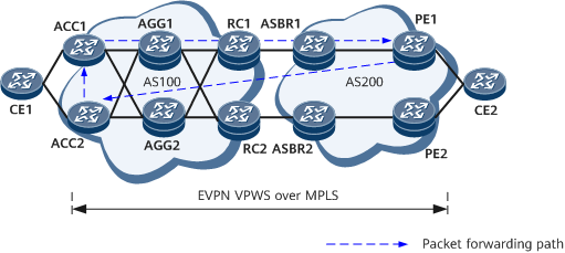
On the network shown in Figure 2, CE1 and CE2 are user-side access devices and are directly connected to an EVPN VPWS over MPLS network. The EVPN VPWS ping process initiated by ACC1 is as follows:
- ACC1 initiates an EVPN VPWS ping test and searches for an EVPN VPWS tunnel to send packets. In an active-active scenario, a private TLV is used to carry the local IP address (LSR ID). In an inter-AS scenario, the control word must be specified and encapsulated.
- After receiving the MPLS Echo Request packet, PE1 verifies the FEC and returns an MPLS Echo Reply packet. If the MPLS Echo Request packet carries the REPLY_ADDRESS_TLV field, PE1 encapsulates the source LSR ID into the MPLS Echo Request packet and does not carry the RA option in the MPLS Echo Reply packet.
- After receiving the response packet, ACC1 displays the information, or ACC2 forwards the response packet to ACC1 based on the destination IP address.
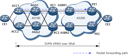
On the network shown in Figure 3, CE1 and CE2 are user-side access devices and are directly connected to an EVPN VPWS over SRv6 network. The EVPN VPWS ping process initiated by ACC1 is as follows:
- ACC1 initiates an EVPN VPWS ping test and searches for an EVPN VPWS tunnel to send packets. In an active-active scenario, a private TLV needs to carry the local VPN SID.
- After receiving the MPLS Echo Request packet, PE1 verifies the FEC and returns an MPLS Echo Reply packet. If the MPLS Echo Reply packet carries the REPLY_ADDRESS_TLV field, PE1 selects a return tunnel based on the VPN SID of the source end.
- ACC1 receives the response packet and displays the information.
Working process of EVPN VPWS tracert in an inter-AS active-active scenario
Figure 2 shows the EVPN VPWS tracert process initiated by ACC1.
- ACC1 initiates an EVPN VPWS tracert test and searches for an EVPN VPWS tunnel to send packets. In an active-active scenario, a private TLV needs to carry the local IP address (LSR ID). In an inter-AS scenario, the control word needs to be specified and encapsulated.
- AGG1 sends the packets to the CPU based on TTL timeout and replies with response packets through routes. The rest may be deduced by analogy until the request packet reaches PE1.
- After receiving the MPLS Echo Request packet, PE1 verifies the FEC and returns an MPLS Echo Reply packet. If the MPLS Echo Request packet carries the REPLY_ADDRESS_TLV field, PE1 encapsulates the source LSR ID into the MPLS Echo Request packet and does not carry the RA option in the MPLS Echo Reply packet.
- After receiving the response packet, ACC1 displays the information, or ACC2 forwards the response packet to ACC1 based on the destination IP address.
Figure 3 shows the EVPN VPWS tracert process initiated by ACC1.
- ACC1 initiates an EVPN VPWS ping test and searches for an EVPN VPWS tunnel to send packets. In an active-active scenario, a private TLV needs to carry the local VPN SID.
- AGG1 sends the packets to the CPU based on TTL timeout and replies with response packets through routes. The rest may be deduced by analogy until the request packet reaches PE1.
- After receiving the MPLS Echo Request packet, PE1 verifies the FEC and returns an MPLS Echo Reply packet. If the MPLS Echo Reply packet carries the REPLY_ADDRESS_TLV field, PE1 selects a return tunnel based on the VPN SID of the source end.
- ACC1 receives the response packet and displays the information.