Layer 2 Protocol Tunneling Fundamentals
When Layer 2 PDUs enter a backbone network:
The ingress device replaces the multicast destination MAC address in the Layer 2 PDUs with a specified multicast MAC address so that it does not send the Layer 2 PDUs to its CPU for processing.

The specified multicast MAC address cannot be a multicast MAC address used by well-known protocols.
- The ingress device then determines whether to add an outer VLAN tag to the Layer 2 PDUs with a specified multicast MAC address based on the configured Layer 2 protocol tunneling type.
When Layer 2 PDUs leave the backbone network:
- The egress device restores the original multicast destination MAC address in the Layer 2 PDUs based on the configured mapping between the multicast destination MAC address and the specified multicast MAC address.
- The egress device then determines whether to remove the outer VLAN tag from the Layer 2 PDUs with the original multicast destination MAC address based on the configured Layer 2 protocol tunneling type.
Table 1 describes the Layer 2 protocol tunneling types that Huawei devices support.
Layer 2 Protocol Tunneling Type |
Usage Scenario |
|---|---|
Backbone network edge devices receive untagged Layer 2 PDUs. |
|
Backbone network edge devices receive Layer 2 PDUs that carry a single VLAN tag. |
|
Backbone network edge devices receive Layer 2 PDUs that carry a single VLAN tag and need to tunnel Layer 2 PDUs that carry double VLAN tags. |
|
Backbone network edge devices receive both tagged and untagged Layer 2 PDUs. |
Untagged Layer 2 Protocol Tunneling
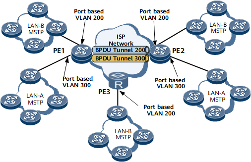
On the network shown in Figure 1, each PE interface connects to one user network, and each user network belongs to either LAN-A or LAN-B. Layer 2 PDUs from user networks to PEs on the backbone network do not carry VLAN tags. The PEs, however, must identify which LAN the Layer 2 PDUs come from. Layer 2 PDUs from a user network in LAN-A must be sent to the other user networks in LAN-A, but not to the user networks in LAN-B. In addition, Layer 2 PDUs cannot be processed by PEs. To meet the preceding requirements, configure interface-based Layer 2 protocol tunneling on backbone network edge devices.
The ingress device on the backbone network identifies the protocol type of the received Layer 2 PDUs and tags them with the default VLAN ID of the interface that has received them.
The ingress device replaces the multicast destination MAC address in the Layer 2 PDUs with a specified multicast MAC address based on the configured mapping between the multicast destination MAC address and the specified multicast MAC address.
The internal devices on the backbone network forward the Layer 2 PDUs with a specified multicast MAC address to the egress devices.
The egress devices restore the original destination MAC address in the Layer 2 PDUs based on the configured mapping between the multicast destination MAC address and the specified multicast address and send the Layer 2 PDUs to the user networks.
VLAN-based Layer 2 Protocol Tunneling
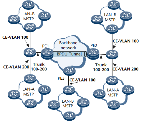
In most circumstances, PEs serve as aggregation devices on a backbone network. On the network shown in Figure 2, the aggregation interfaces on PE1 and PE2 receive Layer 2 PDUs from both LAN-A and LAN-B. To differentiate between the Layer 2 PDUs of the two LANs, the PEs must identify tagged Layer 2 PDUs from CEs, with Layer 2 PDUs from LAN-A carrying VLAN 200 and those from LAN-B carrying VLAN 100. To meet the preceding requirements, configure backbone network devices to identify tagged Layer 2 PDUs and allow Layer 2 PDUs carrying specified VLAN IDs to pass through and also configure VLAN-based Layer 2 protocol tunneling on backbone network edge devices.
User network devices send Layer 2 PDUs with specified VLAN IDs to the backbone network.
The ingress device on the backbone network identifies that the Layer 2 PDUs carry a single VLAN tag and replaces the multicast destination MAC address in the Layer 2 PDUs with a specified multicast MAC address based on the configured mapping between the multicast destination MAC address and the specified multicast MAC address.
The internal devices on the backbone network forward the Layer 2 PDUs with a specified multicast MAC address to the egress devices.
The egress devices restore the original destination MAC address in the Layer 2 PDUs based on the configured mapping between the multicast destination MAC address and the specified multicast address and send the Layer 2 PDUs to the user networks.
QinQ-based Layer 2 Protocol Tunneling
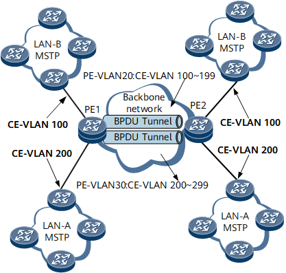
If VLAN-based Layer 2 protocol tunneling is used when many user networks connect to a backbone network, a large number of VLAN IDs of the backbone network are required. This may result in insufficient VLAN resources. To reduce the consumption of VLAN resources, configure QinQ on the backbone network to forward Layer 2 PDUs.
On the network shown in Figure 3, after QinQ is configured, a PE adds an outer VLAN ID of 20 to the received Layer 2 PDUs that carry VLAN IDs in the range 100 to 199 and an outer VLAN ID of 30 to the received Layer 2 PDUs that carry VLAN IDs in the range 200 to 299 before transmitting these Layer 2 PDUs across the backbone network. To tunnel Layer 2 PDUs from the user networks across the backbone network, configure QinQ-based Layer 2 protocol tunneling on PEs' aggregation interfaces.
The ingress device on the backbone network adds a different outer VLAN tag (public VLAN ID) to the received Layer 2 PDUs based on the inner VLAN IDs (user VLAN IDs) carried in the PDUs.
The ingress device replaces the multicast destination MAC address in the Layer 2 PDUs with a specified multicast MAC address based on the configured mapping between the multicast destination MAC address and the specified multicast MAC address.
The ingress device transmits the Layer 2 PDUs with a specified multicast MAC address through different Layer 2 tunnels based on the outer VLAN IDs.
The internal devices on the backbone network forward the Layer 2 PDUs with a specified multicast MAC address to the egress devices.
The egress devices restore the original destination MAC address in the Layer 2 PDUs based on the configured mapping between the multicast destination MAC address and the specified multicast address, remove the outer VLAN tags, and send the Layer 2 PDUs to the user networks based on the inner VLAN IDs.
Hybrid VLAN-based Layer 2 Protocol Tunneling
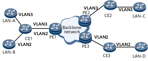
On the network shown in Figure 4, PE1, PE2, and PE3 constitute a backbone network. LAN-A and LAN-C belong to VLAN 3; LAN-B and LAN-D belong to VLAN 2. All LANs send tagged Layer 2 PDUs. CE1 can forward Layer 2 PDUs carrying VLAN 2 and VLAN 3. CE2 can forward Layer 2 PDUs carrying VLAN 3. CE3 can forward Layer 2 PDUs carrying VLAN 2. CE1, CE2, and CE3 also run an untagged Layer 2 protocol, such as LLDP.
PEs therefore receive both tagged and untagged Layer 2 PDUs. To transparently transmit both tagged and untagged Layer 2 PDUs, configure hybrid VLAN-based Layer 2 protocol tunneling on backbone network edge devices.
Hybrid VLAN-based Layer 2 protocol tunneling functions as a combination of interface-based and VLAN-based Layer 2 protocol tunneling. For details about the tunneling process, see Untagged Layer 2 Protocol Tunneling and VLAN-based Layer 2 Protocol Tunneling.