RSTP Implementation
RSTP implementation covers three aspects: P/A mechanism, RSTP topology change operation, and interoperability between RSTP and STP.
P/A Mechanism
To allow a Huawei device to communicate with a non-Huawei device, a proper rapid transition mechanism needs to be configured on the Huawei device based on the Proposal/Agreement (P/A) mechanism on the non-Huawei device.
The P/A mechanism helps a designated port to enter the Forwarding state as soon as possible. As shown in Figure 1, the P/A negotiation is performed based on the following port variables:
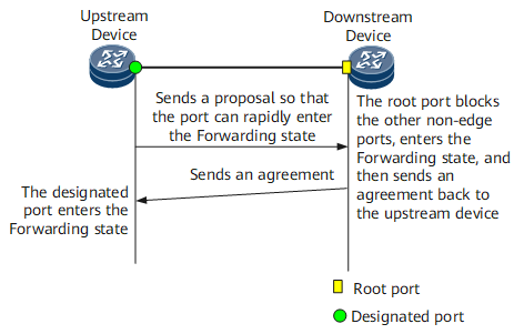
- proposing: When a port is in the Discarding or Learning state, this variable is set to 1. Additionally, a Rapid Spanning Tree (RST) BPDU with the Proposal field being 1 is sent to the downstream device.
- proposed: After a port receives an RST BPDU with the Proposal field being 1 from the designated port on the peer device, this variable is set to 1, urging the designated port on this network segment to enter the Forwarding state.
- sync: After the proposed variable is set to 1, the root port receiving the proposal sets the sync variable to 1 for the other ports on the same device; a non-edge port receiving the proposal enters the Discarding state.
- synced: After a port enters the Discarding state, it sets its synced variable to 1 in the following manner: If this port is the alternate, backup, or edge port, it will immediately set its synced variable to 1. If this port is the root port, it will monitor the synced variables of the other ports. After the synced variables of all the other ports are set to 1, the root port sets its synced variable to 1, and sends an RST BPDU with the Agreement field being 1.
- agreed: After the designated port receives an RST BPDU with the Agreement field being 1 and the port role field indicating the root port, this variable is set to 1. Once the agreed variable is set to 1, this designated port immediately enters the Forwarding state.
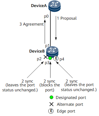
- p0 and p1 become designated ports and send RST BPDUs.
- After receiving an RST BPDU with a higher priority, p1 realizes that it will become a root port but not a designated port, and therefore it stops sending RST BPDUs.
- p0 enters the Discarding state, and sends RST BPDUs with the Proposal field being 1.
- After receiving an RST BPDU with the Proposal field being 1, Device B sets the sync variable to 1 for all its ports.
- As p2 has been blocked, its status keeps unchanged; p4 is an edge port, and therefore it does not participate in calculation. Therefore, only the non-edge designated port p3 needs to be blocked.
- After p2, p3, and p4 enter the Discarding state, their synced variables are set to 1. The synced variable of the root port p1 is then set to 1, and p1 sends an RST BPDU with the Agreement field being 1 to Device A. Except for the Agreement field, which is set to 1, and the Proposal field, which is set to 0, the RST BPDU is the same as that was received.
- After receiving this RST BPDU, Device A identifies it as a reply to the proposal that it just sent, and therefore p0 immediately enters the Forwarding state.
This P/A negotiation process finishes, and Device B continues to perform the P/A negotiation with its downstream device.
Theoretically, STP can quickly select a designated port. To prevent loops, STP has to wait for a period of time long enough to determine the status of all ports on the network. All ports can enter the Forwarding state at least one forward delay later. RSTP is developed to eliminate this bottleneck by blocking non-root ports to prevent loops. By using the P/A mechanism, the upstream port can rapidly enter the Forwarding state.
RSTP Topology Change
In RSTP, if a non-edge port changes to the Forwarding state, the topology changes.
Start a TC While Timer for every non-edge port. The TC While Timer value doubles the Hello Timer value.
All MAC addresses learned by the ports whose status changes are cleared before the timer expires.
These ports send RST BPDUs with the TC field being 1. Once the TC While Timer expires, they stop sending the RST BPDUs.
After another device receives the RST BPDU, it clears the MAC addresses learned by all ports excluding the one that receives the RST BPDU and the edge. The device then starts a TC While Timer for all non-edge ports and the root port, the same as the preceding process.
In this manner, RST BPDUs flood the network.

To use the P/A mechanism, ensure that the link between the two devicesis a point to point (P2P) link in full-duplex mode. Once the P/A negotiation fails, a designated port can forward traffic only after the forwarding delay timer expires twice. This delay time is the same as that in STP.
Interoperability Between RSTP and STP
When RSTP switches to STP, RSTP loses its advantages such as fast convergence.
On a network where both STP-enabled and RSTP-enabled devices are deployed, STP-enabled devices ignore RST BPDUs; if a port on an RSTP-enabled device receives a configuration BPDU from an STP-enabled device, the port switches to the STP mode after two Hello intervals and starts to send configuration BPDUs. In this manner, RSTP and STP are interoperable.
After STP-enabled devices are removed, Huawei RSTP-enabled datacom devices can switch back to the RSTP mode from the STP mode by running a command.