Evolution from STP to RSTP
In 2001, IEEE 802.1w was published to introduce an extension of the Spanning Tree Protocol (STP), namely, Rapid Spanning Tree Protocol (RSTP). RSTP is developed based on STP but outperforms STP.
Disadvantages of STP
STP ensures a loop-free network but has a slow network topology convergence speed, leading to service deterioration. If the network topology changes frequently, the connections on the STP-enabled network are frequently torn down, causing frequent service interruption. Users can hardly tolerate such a situation.
Disadvantages of STP are as follows:
Port states or port roles are not subtly distinguished, which is not conducive to the learning and deployment for beginners.
A network protocol that subtly defines and distinguishes different situations is likely to outperform the others.
Ports in the Listening, Learning, and Blocking states do not forward user traffic and are not even slightly different to users.
The differences between ports in essence never lie in the port states but the port roles from the perspective of use and configuration.
It is possible that the root port and designated port are both in the Listening state or Forwarding state.
The STP algorithm determines topology changes after the time set by the timer expires, which slows down network convergence.
The STP algorithm requires a stable network topology. After the root bridge sends configuration Bridge Protocol Data Units (BPDUs), other devices forward them until all bridges on the network receive the configuration BPDUs.
This also slows down topology convergence.
Advantages of RSTP over STP
To make up for STP disadvantages, Rapid Spanning Tree Protocol (RSTP) deletes three port states, introduces two port roles, and distinguishes port attributes based on port states and roles to provide more accurate port description. This offers beginners easy access to protocols and speeds up topology convergence.
More port roles are defined to simplify the knowledge and deployment of STP.
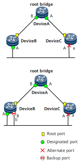
As shown in Figure 1, RSTP defines four port roles: root port, designated port, alternate port, and backup port.
The functions of the root port and designated port are the same as those defined in STP. The alternate port and backup port are described as follows:- From the perspective of configuration BPDU transmission:
- An alternate port is blocked after learning the configuration BPDUs sent by other bridges.
- A backup port is blocked after learning the configuration BPDUs sent by itself.
- From the perspective of user traffic
- An alternate port backs up the root port and provides an alternate path from the designated bridge to the root bridge.
- A backup port backs up the designated port and provides an alternate path from the root bridge to the related network segment.
After all RSTP-enabled ports are assigned roles, topology convergence is completed.
Port states are redefined in RSTP.
Port states are simplified from five types to three types. Based on whether a port forwards user traffic and learns MAC addresses, the port is in one of the following states:
- If a port neither forwards user traffic nor learns MAC addresses, the port is in the Discarding state.
- If a port does not forward user traffic but learns MAC addresses, the port is in the Learning state.
- If a port forwards user traffic and learns MAC addresses, the port is in the Forwarding state.
Table 1 shows the comparison between port states in STP and RSTP.

Port states and port roles are not necessarily related. Table 1 lists states of ports with different roles.
Table 1 Comparison between states of STP ports and RSTP ports with different roles STP Port State
RSTP Port State
Port Role
Forwarding
Forwarding
Root port or designated port
Learning
Learning
Root port or designated port
Listening
Discarding
Root port or designated port
Blocking
Discarding
Alternate port or backup port
Disabled
Discarding
Disabled port
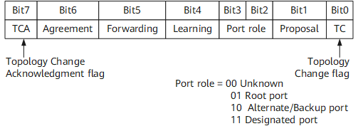
Configuration BPDUs in RSTP are differently defined. Port roles are described based on the Flags field defined in STP.
Compared with STP, RSTP slightly redefined the format of configuration BPDUs.- The value of the Type field is no longer set to 0 but 2. Therefore, the RSTP-enabled device always discards the configuration BPDUs sent by an STP-enabled device.
- The 6 bits in the middle of the original Flags field are reserved. Such a configuration BPDU is called an RST BPDU, as shown in Figure 2.
- Configuration BPDUs are processed in a different manner.
Transmission of configuration BPDUs
In STP, after the topology becomes stable, the root bridge sends configuration BPDUs at an interval set by the Hello timer. A non-root bridge does not send configuration BPDUs until it receives configuration BPDUs sent from the upstream device. This renders the STP calculation complicated and time-consuming. In RSTP, after the topology becomes stable, a non-root bridge sends configuration BPDUs at Hello intervals, regardless of whether it has received the configuration BPDUs sent from the root bridge. Such operations are implemented on each device independently.
BPDU timeout period
In STP, a device has to wait a Max Age period before determining a negotiation failure. In RSTP, if a port does not receive configuration BPDUs sent from the upstream device for three consecutive Hello intervals, the negotiation between the local device and its peer fails.
Processing of inferior BPDUs
In RSTP, when a port receives an RST BPDU from the upstream designated bridge, the port compares the received RST BPDU with its own RST BPDU.
If its own RST BPDU is superior to the received one, the port discards the received RST BPDU and immediately responds to the upstream device with its own RST BPDU. After receiving the RST BPDU, the upstream device updates its own RST BPDU based on the corresponding fields in the received RST BPDU.
In this manner, RSTP processes inferior BPDUs more rapidly, independent of any timer that is used in STP.
Rapid convergence
Proposal/agreement mechanism
When a port is selected as a designated port, in STP, the port does not enter the Forwarding state until a Forward Delay period expires; in RSTP, the port enters the Discarding state, and then the proposal/agreement mechanism allows the port to immediately enter the Forwarding state. The proposal/agreement mechanism must be applied on the P2P links in full duplex mode.
For details, see RSTP Implementation.
Fast switchover of the root port
If the root port fails, the most superior alternate port on the network becomes the root port and enters the Forwarding state. This is because there must be a path from the root bridge to a designated port on the network segment connecting to the alternate port.
When the port role changes, the network topology will change accordingly. For details, see RSTP Implementation.
Edge ports
In RSTP, a designated port on the network edge is called an edge port. An edge port directly connects to a terminal and does not connect to any other devices.
An edge port does not receive configuration BPDUs, and therefore does not participate in the RSTP calculation. It can directly change from the Disabled state to the Forwarding state without any delay, just like an STP-incapable port. If an edge port receives bogus BPDUs from attackers, it is deprived of the edge port attributes and becomes a common STP port. The STP calculation is implemented again, causing network flapping.
Protection functions
Table 2 shows protection functions provided by RSTP.
Table 2 Protection functions Protection Function
Scenario
Principle
BPDU protection
On a device, ports that are directly connected to a user terminal such as a PC or file server are configured as edge ports.
Usually, no Rapid Spanning Tree (RST) BPDU will be sent to edge ports. If a device receives bogus RST BPDUs on an edge port, the device automatically sets the edge port to a non-edge port, and performs STP calculation again. This causes network flapping.
After BPDU protection is enabled on a device, if an edge port receives an RST BPDU, the device shuts down the edge port without depriving of its attributes, and notifies the NMS of the shutdown event. The edge port can be started only by the network administrator.
To allow an edge port to automatically start after being shut down, you can configure the auto recovery function and set the delay on the port. In this manner, an edge port starts automatically after the set delay. If the edge port receives RST BPDUs again, the edge port will again be shut down.NOTE:The smaller the delay is set, the sooner the edge port becomes Up, and the more frequently the edge port alternates between Up and Down. The larger the delay is set, the later the edge port becomes Up, and the longer the service interruption lasts.
Root protection
Due to incorrect configurations or malicious attacks on the network, the root bridge may receive RST BPDUs with a higher priority. Consequently, the valid root bridge is no longer able to serve as the root bridge, and the network topology incorrectly changes. This also causes the traffic that should be transmitted over high-speed links to be transmitted over low-speed links, leading to network congestion.
If a designated port is enabled with the root protection function, the port role cannot be changed. Once a designated port that is enabled with root protection receives RST BPDUs with a higher priority, the port enters the Discarding state and does not forward packets. If the port does not receive any RST BPDUs with a higher priority before a period (generally two Forward Delay periods) expires, the port automatically enters the Forwarding state.NOTE:Root protection can take effect on only designated ports.
Loop protection
On an RSTP-enabled network, the device maintains the status of the root port and blocked ports by continually receiving BPDUs from the upstream device.
If ports cannot receive BPDUs from the upstream device due to link congestion or unidirectional link failures, the device re-selects a root port. Then, the previous root port becomes a designated port and the blocked ports change to the Forwarding state. As a result, loops may occur on the network.
After loop protection is configured, if the root port or alternate port does not receive RST BPDUs from the upstream device for a long time, the device notifies the NMS that the port enters the Discarding state. The blocked port remains in the Blocked state and does not forward packets. This prevents loops on the network. The root port or alternate port restores the Forwarding state after receiving new RST BPDUs.NOTE:Loop protection can take effect on only the root port and alternate ports.
Topology Change (TC) BPDU attack defense
After receiving TC BPDUs, a device will delete its MAC entries and ARP entries. In the event of a malicious attack by sending bogus TC BPDUs, a device receives a large number of TC BPDUs within a short period, and busies itself deleting its MAC entries and ARP entries. As a result, the device is heavily burdened, rendering the network rather unstable.
After the TC BPDU attack defense is enabled, the number of times that TC BPDUs are processed by the device within a given time period is configurable. If the number of TC BPDUs that the device receives within the given time exceeds the specified threshold, the device processes TC BPDUs only for the specified number of times. Excess TC BPDUs are processed by the device as a whole for once after the specified period expires. In this manner, the device is prevented from frequently deleting its MAC entries and ARP entries, and therefore is protected against overburden.