Ethernet Physical Layer
Introduction to Ethernet Cable Standards
The following Ethernet cabling standards exist:
10BASE-2
10BASE-5
10BASE-T
10BASE-F
100BASE-T4
100BASE-TX
100BASE-FX
1000BASE-SX
1000BASE-LX
1000BASE-TX
In these cabling standards, 10, 100, and 1000 represent the transmission rate (in Mbit/s), and BASE represents baseband.
10M Ethernet cable standard
Table 1 lists the 10M Ethernet cabling standard specifications defined in IEEE 802.3.
Table 1 10M Ethernet cable standard Name
Cable
Maximum Transmission Distance
10BASE-5
Thick coaxial cable
500 m
10BASE-2
Thin coaxial cable
200 m
10BASE-T
Twisted pair cable
100 m
10BASE-F
Fiber
2000 m
The greatest limitation of coaxial cable is that devices on the cable are connected in series, so a single point of failure (SPOF) may cause a breakdown of the entire network. As a result, the physical standards of coaxial cables, 10BASE-2 and 10BASE-5, have fallen into disuse.
100M Ethernet cable standard
100M Ethernet is also called Fast Ethernet (FE). Compared with 10M Ethernet, 100M Ethernet has a faster transmission rate at the physical layer, but has the same rate at the data link layer.
Table 2 lists the 100M Ethernet cable standard specifications.
Table 2 100M Ethernet cable standard Name
Cable
Maximum Transmission Distance
100Base-T4
Four pairs of Category 3 twisted pair cables
100 m
100Base-Tx
Two pairs of Category 5 twisted pair cables
100 m
100Base-Fx
Single-mode or multi-mode fiber
2000 m
10Base-T and 100Base-TX have different transmission rates, but both apply to Category 5 twisted pair cables. 10Base-T transmits data at 10 Mbit/s, while 100Base-TX transmits data at 100 Mbit/s.
100Base-T4 is now rarely used.
Gigabit Ethernet cable standard
Gigabit Ethernet developed from the Ethernet standard defined in IEEE 802.3. Based on the Ethernet protocol, Gigabit Ethernet increases the transmission rate to 10 times the FE transmission rate, reaching 1 Gbit/s. Table 3 lists the Gigabit Ethernet cable standard specifications.
Table 3 Gigabit Ethernet cable standard Name
Cable
Maximum Transmission Distance
1000Base-LX
Single-mode or multi-mode fiber
316 m
1000Base-SX
Multi-mode fiber
316 m
1000Base-TX
Category 5 twisted pair cable
100 m
Using Gigabit Ethernet technology, you can upgrade an existing Fast Ethernet network from 100 Mbit/s to 1000 Mbit/s.
Gigabit Ethernet uses 8B10B coding at the physical layer. In traditional Ethernet transmission technologies, the data link layer delivers 8-bit data sets to the physical layer, where they are processed and sent still as 8 bits to the physical link for transmission.
In contrast, on the optical fiber-based Gigabit Ethernet, the physical layer maps the 8-bit data sets transmitted from the data link layer to 10-bit data sets before sending them out.
10GE cable standards
10GE cable standards are numerous and continuously evolving, and include IEEE802.3ae, IEEE802.3an, IEEE 802.3aq, and IEEE 802.3ap. 10GE provides a 10 Gbit/s transmission rate, which overcomes bandwidth and transmission distance problems and enables Ethernet technology to be applied to the backbone and aggregation layers of metro networks. 10GE only supports the full-duplex mode. Table 4 lists the related cable standards.
Table 4 10GE cable standards Name
Cable
Maximum Transmission Distance
10GBase-SR
Multi-mode fiber
300 m
10GBase-LR
Single-mode fiber
10 km
10GBase-LRM
Multi-mode fiber
260 m
10GBase-ER
Single-mode fiber
40 km
10GBase-ZR
Single-mode fiber
80 km
10GBase-LX4
Single-mode or multi-mode fiber
10 km
10GBase-CX4
Shielded twisted pair
15 m
10GBase-T
Category 6 twisted pair
55 m
10GBase-KX4
Copper line
1 m
10GBase-KR
Copper line
1 m
The development of 10GE is well under way, and will be widely deployed in future.
CSMA/CD
Concept of CSMA/CD
Ethernet was originally designed to connect stations, such as computers and peripherals, on a shared physical line. However, the stations can only access the shared line in half-duplex mode. Therefore, a mechanism of collision detection and avoidance is required to enable multiple devices to share the same line in way that gives each device fair access. Carrier Sense Multiple Access with Collision Detection (CSMA/CD) was therefore introduced.
The concept of CSMA/CD is as follows:
CS: carrier sense
Before transmitting data, a station checks to see if the line is idle. In this manner, chances of collision are decreased.
MA: multiple access
The data sent by a station can be received by other stations.
CD: collision detection
If two stations transmit electrical signals at the same time, the signals are superimposed, doubling the normal voltage amplitude. This situation results in collision.
The stations stop transmitting after sensing the conflict, and then resume transmission after a random delay time.
Working process of CSMA/CD
CSMA/CD works as follows:
A station continuously checks whether the shared line is idle.
If the line is idle, the station sends data.
If the line is in use, the station waits until the line is idle.
If two stations send data at the same time, a conflict occurs on the line, and the signal becomes unstable.
After detecting an instability, the station immediately stops sending data.
The station sends a series of pulses.
The pulses inform other stations that a conflict has occurred on the line.
After detecting a conflict, the station waits for a random period of time, and then resumes the data transmission.
Minimum Frame Length and Maximum Transmission Distance
Minimum frame length
Due to the CSMA/CD algorithm limitation, an Ethernet frame cannot be shorter than a certain length. The minimum frame length is 64 bytes. This length was determined based on Ethernet maximum transmission distance and the collision detection mechanism.
The use of a minimum frame length prevents situations in which station A finishes sending the last bit of a frame, but the first bit has not arrived at station B. Station B senses that the line is idle and begins to send data, leading to a conflict.
The upper layer protocol must ensure that each frame's Data field contains at least 46 bytes. As such, a Data field with a 14-byte Ethernet frame header and a 4-byte check code at the end of the frame equals the minimum frame length of 64 bytes. If the Data field is less than 46 bytes, the upper layer protocol must make up the difference.
The maximum length of the Data field is arbitrary, but it has been set to 1500 bytes as required by the memory cost and buffer of low-cost LAN controllers in 1979.
Maximum transmission distance
The maximum transmission distance depends on factors such as line quality and signal attenuation.
Ethernet Duplex Modes
The Ethernet physical layer can work in either half- or full-duplex mode.
Half-duplex mode
Half-duplex mode has the following features:
Sending and receiving data takes place in one direction at a time.
The CSMA/CD mechanism is used.
The transmission distance is limited.
Hubs work in half-duplex mode.
Full-duplex mode
After Layer 2 switches replace hubs, the shared Ethernet changes to the switched Ethernet, and the half-duplex mode is replaced by the full-duplex mode. As a result, the transmission rate of data frames increases significantly, with the maximum throughput doubled.
The full-duplex mode fundamentally solves the problem of collisions on Ethernets and eliminates the need for CSMA/CD.
Full-duplex mode has the following features:
Transmitting and receiving data can take place simultaneously.
The maximum throughput is theoretically twice that of half-duplex mode.
This mode extends the transmission distance of half-duplex mode.
Except for hubs, all network cards, Layer 2 switches, and routers produced in the past 10 years support full-duplex mode.
Full-duplex mode has the following requirements:
Full-duplex network cards and modules
Physical media over which sending and receiving frames are separated
Point-to-point connection
Ethernet Auto-Negotiation
Purpose of auto-negotiation
As the earlier Ethernet utilizes a 10 Mbit/s half-duplex mode, mechanisms such as CSMA/CD are required to guarantee system stability. As technology developed, the full-duplex mode and 100M Ethernet have emerged in succession, both of which have significantly improved Ethernet performance. However, they have also introduced an entirely new problem: achieving compatibility between older and newer Ethernet networks.
The auto-negotiation technology has been introduced to solve this problem. With auto-negotiation, the device at each end of a physical link chooses the same operation parameters by exchanging information. The main parameters to be automatically negotiated include mode (half-duplex or full-duplex), rate, and flow control. Once negotiation completes, the devices operate in the agreed mode and rate.
Principle of auto-negotiation
Auto-negotiation is based on a bottom-layer mechanism of twisted-pair Ethernets, and applies only to such Ethernets.
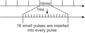
When data is not transmitted over a twisted pair cable, the cable does not remain idle. Instead, it continues transmitting low frequency pulse signals, and any Ethernet adapter with interfaces for twisted pair cables can identify these pulses. The device at each end can also identify lower frequency pulses — referred to as fast link pulses (FLPs) — after such pulses have been inserted. In this way, the devices achieve auto-negotiation by using FLPs to transmit a small amount of data. Figure 1 shows the pulse insertion process.
Auto-negotiation priorities of the Ethernet duplex link are listed as follows in descending order:
1000M full-duplex
1000M half-duplex
100M full-duplex
100M half-duplex
10M full-duplex
10M half-duplex
If auto-negotiation succeeds, the Ethernet card activates the link. Then, data can be transmitted over it. If auto-negotiation fails, the link is inaccessible.
Auto-negotiation is implemented at the physical layer and does not require any data packets or have impact on upper-layer protocols.
Auto-negotiation rules for interfaces
Two connected interfaces can communicate with each other only when they are in the same working mode.- If both interfaces work in the same non-auto-negotiation mode, the interfaces can communicate.
- If both interfaces work in auto-negotiation mode, the interfaces can communicate through negotiation. The negotiated working mode depends on the interface with lower capability. Specifically, if one interface works in full-duplex mode and the other interface works in half-duplex mode, the negotiated working mode is half-duplex. The auto-negotiation function also allows the interfaces to negotiate the use of the traffic control function.
If a local interface works in auto-negotiation mode and the remote interface works in a non-auto-negotiation mode, the negotiated working mode of the local interface depends on the working mode of the remote interface.
Table 5 describes the auto-negotiation rules for interfaces of the same type.
Table 5 Auto-negotiation rules for interfaces of the same type (local interface working in auto-negotiation mode) Interface Type
Working Mode of the Remote Interface
Auto-negotiation Result
Description
FE electrical interface
10M half-duplex
10M half-duplex
If the remote interface works in 10M full-duplex or 100M full-duplex mode, the working modes of the two interfaces are different after auto-negotiation, and packets may be dropped. Therefore, if the remote interface works in 10M full-duplex or 100M full-duplex mode, configure the local interface to work in the same mode.
10M full-duplex
10M half-duplex
100M half-duplex
100M half-duplex
100M full-duplex
100M half-duplex
GE electrical interface
FE auto-negotiation
100M full-duplex
If the remote interface works in 10M full-duplex or 100M full-duplex mode, the working modes of the two interfaces are different after auto-negotiation, and packets may be dropped. Therefore, if the remote interface works in 10M full-duplex or 100M full-duplex mode, configure the local interface to work in the same mode.
10M half-duplex
10M half-duplex
10M full-duplex
10M half-duplex
100M half-duplex
100M half-duplex
100M full-duplex
100M half-duplex
1000M full-duplex
1000M full-duplex
Table 6 describes the auto-negotiation rules for interfaces of different types.
Table 6 Auto-negotiation rules for interfaces of different types Interface Type
Working Mode of an FE Electrical Interface
Working Mode of a GE Electrical Interface
Auto-negotiation Result
Description
An FE electrical interface connecting to a GE electrical interface
10M half-duplex
Auto-negotiation
10M half-duplex
If the FE electrical interface works in 10M full-duplex or 100M full-duplex mode and the GE electrical interface works in auto-negotiation mode, the working modes of the two interfaces are different after auto-negotiation and packets may be dropped. Therefore, if the FE electrical interface works in 10M full-duplex or 100M full-duplex mode, configure the GE electrical interface to work in the same mode.
10M full-duplex
10M half-duplex
100M half-duplex
100M half-duplex
100M full-duplex
100M half-duplex
Auto-negotiation
10M half-duplex
10M half-duplex
If the FE electrical interface works in auto-negotiation mode and the GE electrical interface works in 10M full-duplex or 100M full-duplex mode, the working modes of the two interfaces are different after auto-negotiation, and packets may be dropped. Therefore, if the GE electrical interface works in 10M full-duplex or 100M full-duplex mode, configure the FE electrical interface to work in the same mode.
If you configure the GE electrical interface to work in 1000M full-duplex mode, auto-negotiation fails.
10M full-duplex
10M half-duplex
100M half-duplex
100M half-duplex
100M full-duplex
100M half-duplex
1000M full-duplex
Failure
According to the auto-negotiation rules described in Table 5 and Table 6, if an interface works in auto-negotiation mode and the connected interface works in a non-auto-negotiation mode, packets may be dropped or auto-negotiation may fail. It is recommended that you configure two connected interfaces to work in the same mode to ensure that they can communicate properly.
FE and higher-rate optical interfaces only support full-duplex mode. Auto-negotiation is enabled on GE optical interfaces only for the negotiation of flow control only. When devices are directly connected using GE optical interfaces, auto-negotiation is enabled on the optical interfaces to detect unidirectional optical fiber faults. If one of two optical fibers is faulty, the fault information is synchronized on both ends through auto-negotiation. As a result, interfaces on both ends go Down. After the fault is rectified, the interfaces go Up again through auto-negotiation.
HUB
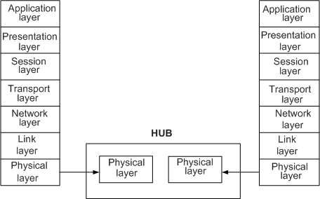
Hub principle
When terminals are connected through twisted pair cables, a convergence device called a hub is required. Hubs operate at the physical layer. Figure 2 shows a hub operation model.
A hub is configured as a box with multiple interfaces, each of which can connect to a terminal. Therefore, multiple devices can be connected through a hub to form a star topology.
Note that although the physical topology is a star, the hub uses bus and CSMA/CD technologies.
Figure 3 Hub operation principle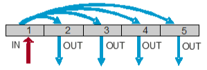
- Two types of hubs are possible, distinguished by their interfaces:
Category-I hub: provides a single type of physical interfaces.
For example, a Category-I hub can accommodate either Category-5 twisted pair interfaces, Category-3 twisted pair interfaces, or optical fiber interfaces.
Category-II hub: provides interfaces of different types. For example, a Category-II hub can provide both Category-5 twisted pair interfaces and optical fiber interfaces.
Aside from the interface provision, these hub types have no differences in their internal operation. In practice, Category-I hubs are commonly used.