Ethernet Data Link Layer
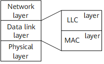
Hierarchical Structure of the Data Link Layer
In Ethernet, the following access modes are used according to different duplex modes:
CSMA/CD is used in half-duplex mode.
Data is sent in full-duplex mode without having to detect if the line is idle.
Duplex mode, either half or full, refers to the operation mode of the physical layer. Access mode refers to the access of the data link layer. Therefore, in the Ethernet, the data link layer and physical layer are associated.
Therefore, different access modes are required for different operation modes. This brings about some inconvenience to the design and application of the Ethernet.
Some organizations and vendors have proposed dividing the data link layer into two sub-layers: the Logical Link Control (LLC) sub-layer and the Media Access Control (MAC) sub-layer. Then, different physical layers correspond to different MAC sub-layers, and the LLC sub-layer becomes totally independent, as shown in Figure 1.
MAC Sub-layer
Functions of the MAC sub-layer
The MAC sub-layer is responsible for the following:
Accessing physical links
Identifying stations at the data link layer
The MAC sub-layer reserves a unique MAC address to identify each station.
Transmitting data over the data link layer. After receiving data from the LLC sub-layer, the MAC sub-layer adds the MAC address and control information to the data, and then transfers the data to the physical link. During this process, the MAC sub-layer provides other functions, such as the check function.
Accessing physical links
The MAC sub-layer is associated with the physical layer so that different MAC sub-layers provide access to different physical layers.
Ethernet has two types of MAC sub-layers:
Half-duplex MAC: provides access to the physical layer in half-duplex mode.
Full-duplex MAC: provides access to the physical layer in full-duplex mode.
The two types of MAC are integrated in a network interface card. After the network interface card is initialized, auto-negotiation is performed to choose an operation mode, and then a MAC is chosen according to the operation mode.
Identifying stations at the data link layer
The MAC sub-layer uses a MAC address to uniquely identify a station.
MAC addresses are managed by the Institute of Electrical and Electronics Engineers (IEEE) and allocated in blocks. An organization, generally a vendor, obtains a unique address block from the IEEE. The address block is called the Organizationally Unique Identifier (OUI), and can be used by the organization to allocate addresses to 16,777,216 devices.
A MAC address consists of 48 bits, generally represented in dotted hexadecimal notation. For example, the 48-bit MAC address 000000001110000011111100001110011000000000110100 is generally represented as 00e0.fc39.8034.
The first 24 bits stand for the OUI; the last 24 bits are allocated by the vendor. For example, in 00e0.fc39.8034, 00e0.fc is the OUI allocated by the IEEE to Huawei; 39.8034 is the address number allocated by Huawei.
The second bit of a MAC address indicates whether the address is globally or locally unique. The Ethernet uses globally unique MAC addresses.
Ethernet uses the following types of MAC addresses:
Physical MAC address
A physical MAC address is permanently stored in network interface hardware (such as a network interface card) and is used to uniquely identify a terminal on an Ethernet.
Broadcast MAC address
A broadcast MAC address indicates all the terminals on a network.
The 48 bits of a broadcast MAC address are all 1s. In hexadecimal notation, this address is ffff.ffff.ffff.
Multicast MAC address
A multicast MAC address indicates a group of terminals on a network.
The eighth bit of a multicast MAC address is 1, such as 000000011011101100111010101110101011111010101000.
Transmitting data at the data link layer
Data transmission at the data link layer is as follows:
The upper layer delivers data to the MAC sub-layer.
The MAC sub-layer stores the data in a buffer.
The MAC sub-layer adds the destination and source MAC addresses to the data, calculates the length of the data frame, and forms Ethernet frames.
The Ethernet frame is sent to the peer according to the destination MAC address.
The peer compares the destination MAC address with entries in the MAC address table.
If there is a matching entry, the frame is accepted.
If there is no matching entry, the frame is discarded.
The preceding describes frame transmission in unicast mode. After an upper-layer application is added to a multicast group, the data link layer generates a multicast MAC address according to the application, and then adds the multicast MAC address to the MAC address table. The MAC sub-layer then receives frames with the multicast MAC address and transmits the frames to the upper layer.
Ethernet Frame Structure
Format of an Ethernet_II frame
Figure 2 Format of an Ethernet_II frame
An Ethernet_II frame has the following fields:
DMAC
Indicates the destination MAC address, which specifies the receiver of the frame.
SMAC
Indicates the source MAC address, which specifies the sender of the frame.
Type
The 2-byte Type field identifies the upper layer protocol of the Data field. The receiver can interpret the meaning of the Data field according to the Type field.
Multiple protocols can coexist on a local area network (LAN). The hexadecimal values in the Type field of an Ethernet_II frame specify different protocols.
Frames with the Type field value 0800 are IP frames.
Frames with the Type field value 0806 are Address Resolution Protocol (ARP) frames.
Frames with the Type field value 0835 are Reverse Address Resolution Protocol (RARP) frames.
Frames with the Type field value 8137 are Internetwork Packet Exchange (IPx) and Sequenced Packet Exchange (SPx) frames.
Data
The minimum length of the Data field is 46 bytes, which ensures that the frame is at least 64 bytes in length. A 46-byte Data field is required even if a station transmits 1 byte of data.
If the payload of the Data field is less than 46 bytes, the Data field must be padded to 46 bytes.
The maximum length of the Data field is 1500 bytes.
CRC
The Cyclic Redundancy Check (CRC) field provides an error detection mechanism.
Each sending device calculates a CRC code from the DMAC, SMAC, Type, and Data fields. Then the CRC code is filled into the 4-byte CRC field.
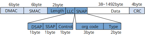
Format of an IEEE 802.3 frame
As shown in Figure 3, the format of an IEEE 802.3 frame is similar to that of an Ethernet_II frame. In an IEEE 802.3 frame, however, the Type field is changed to the Length field, and the LLC field and Sub-Network Access Protocol (SNAP) field occupy 8 bytes of the Data field.
Length
The Length field specifies the number of bytes of the Data field.
LLC
The LLC field consists of three sub-fields: Destination Service Access Point (DSAP), Source Service Access Point (SSAP), and Control.
SNAP
The SNAP field consists of the Org Code field and Type field. Three bytes of the Org Code field are all 0s. The Type field functions the same as that in Ethernet_II frames.
For descriptions of other fields, see the description of Ethernet_II frames.
Based on the values of DSAP and SSAP, IEEE 802.3 networks use the following types of frames:
If DSAP and SSAP are both 0xff, the IEEE 802.3 frame becomes a NetWare-Ethernet frame bearing NetWare data.
If DSAP and SSAP are both 0xaa, the IEEE 802.3 frame becomes an Ethernet_SNAP frame.
Ethernet_SNAP frames can encapsulate the data of multiple protocols. The SNAP can be considered as an extension of the Ethernet protocol. SNAP allows vendors to invent their own Ethernet transmission protocols.
The Ethernet_SNAP standard is defined by IEEE 802.1 to help ensure compatibility between the operations between IEEE 802.3 LANs and Ethernet networks.
Other values of DSAP and SSAP indicate IEEE 802.3 frames.
Jumbo frames
Jumbo frames are Ethernet frames of greater length complying with vendor standards. Such frames are dedicated to Gigabit Ethernet.
Jumbo frames carry more than 1518 bytes of payload. Generally, Ethernet frames carry a maximum payload of 1518 bytes. Therefore, to implement transmission of large-sized datagrams at the IP layer, datagram fragmentation is required to transmit the data within an Ethernet frame. A frame header and a framer trailer are added to each frame during frame transmission. Therefore, to reduce network costs and improve network usage and transmission rate, Jumbo frames are introduced.
The two Ethernet interfaces that need to communicate must both support jumbo frames so that NetEngine 8000 Fs can merge several standard-sized Ethernet frames into a jumbo frame to improve transmission efficiency.
The default value of the Jumbo frame is 10000 bytes.
LLC Sub-layer
As described, the MAC sub-layer supports IEEE 802.3 frames and Ethernet_II frames. In an Ethernet_II frame, the Type field identifies the upper layer protocol. Therefore, on a device, the LLC sub-layer is not needed and only the MAC sub-layer is required.
In an IEEE 802.3 frame, useful features are defined at the LLC sub-layer in addition to the traditional services of the data link layer. These features are specified by the sub-fields of DSAP, SSAP, and Control.
Networks can support the following types of point-to-point services:
Connection-less service
Currently, the Ethernet implements this service.
Connection-oriented service
The connection is set up before data is transmitted. The reliability of the data transmission is ensured.
Connection-less data transmission with acknowledgment
The connection is not required before data transmission. The acknowledgment mechanism is adopted to improve reliability.
The following is an example describing the application of SSAP and DSAP with terminals A and B that use connection-oriented services. Data is transmitted using the following process:
A sends a frame to B to request a connection with B.
After receiving the frame, if B has enough resources, B returns an acknowledgment message that contains a Service Access Point (SAP). The SAP identifies the connection required by A.
After receiving the acknowledgment message, A knows that B has set up a local connection between them. After creating a SAP, A sends a message containing the SAP to B. The connection is set up.
The LLC sub-layer of A encapsulates the data into a frame. The DSAP field is filled in with the SAP sent by B; the SSAP field is filled in with that created by A. Then the LLC sub-layer of A transfers the data to its MAC sub-layer.
The MAC sub-layer of A adds the MAC address and Length field to the frame, and then transfers the frame to the data link layer.
After the frame is received at the MAC sub-layer of B, the frame is transferred to the LLC sub-layer. The LLC sub-layer identifies the connection that the frame belongs to according to the DSAP field.
After checking and acknowledging the frame based on the connection type, the LLC sub-layer of B transfers the frame to the upper layer.
After the frame reaches its destination, A sends B a frame instructing B to release the connection. At this time, the communications end.