ICMP Jitter Test
Implementation Principle
An Internet Control Message Protocol (ICMP) jitter test calculates the delay, jitter, and packet loss rate using timestamps carried in ICMP packets. The jitter time is the interval for receiving two consecutive packets minus the interval for sending them. Figure 1 shows the ICMP jitter test process.
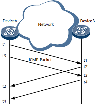
Source (Device A) adds timestamp t1 to an ICMP packet and sends the packet to Destination (Device B).
Upon receipt of the packet, Destination (Device B) adds timestamp t1' to the packet.
After processing the packet, Destination (Device B) adds timestamp t2' to the packet and forwards it back to Source (Device A).
Upon receipt of the packet, Source (Device A) adds timestamp t2 to the packet. (Timestamps t3/t3' and t4/t4' are similar.)
Maximum, minimum, and average jitter of the packets from the source to the destination and from the destination to the source.
Maximum one-way delay time of the packets that the source sends to the destination or the destination sends to the source.
Related Concepts
Source-to-destination jitter = (t3' – t1') – (t3 – t1)
A larger absolute jitter value indicates poorer link quality, no matter whether the jitter value is positive or negative.
Destination-to-source jitter = (t4 – t2) – (t4' – t2')
A larger absolute jitter value indicates poorer link quality, no matter whether the jitter value is positive or negative.
RTT = (t2 – t1) – (t2'- t1')
If the RTT is longer than the specified timeout period, the network is congested and ICMP packets will be counted as lost packets.
Packet loss rate = Number of lost ICMP packets/Number of sent ICMP packets (Number of lost ICMP packets = Number of sent ICMP packets – Number of received ICMP packets).
In an ICMP jitter test, you can set the number of packets to be sent consecutively in a single test instance to simulate a certain type of traffic.
Hardware-based ICMP Jitter Test
Reduces the interval at which packets are sent. The minimum interval is 10 ms.
Increases the number of concurrent test instances. To increase the number of concurrent test instances, install more interface boards on a device.
Increases the accuracy of the calculated delay and jitter time.
Maximum, minimum, and average jitter values of the packets exchanged between the source and destination
Maximum one-way delay time of the packets that the source sends to the destination or the destination sends to the source
The obtained jitter value reflects the network status.
Item |
ICMP Jitter |
ICMP Jitter (hardware-based) |
|---|---|---|
Minimum interval at which test packets are sent |
20 ms |
10 ms |
Maximum number of concurrent test instances |
100 concurrent test instances on each device |
The number of concurrent test instances increases with the number of boards. |
Jitter calculation |
The main control board timestamps packets. |
The interface board timestamps packets more precisely. |
ICMP Jitter (receive-timestamp-unit)
ICMP jitter (receive-timestamp-unit) is a supplement to the ICMP jitter (hardware-based). It also uses the hardware forwarding engine to send packets and add timestamps for the interconnection with a non-Huawei device that functions as a destination (server).
Compared with ICMP jitter (hardware-based), ICMP jitter (receive-timestamp-unit) has the following differences:
ICMP jitter (receive-timestamp-unit) supports the interconnection with a non-Huawei device that functions as a destination (server). ICMP jitter (hardware-based) supports the interconnection with a Huawei device that functions as a destination (server) only.
To parse the timestamp of the ICMP timestamp packet returned by the destination (server), ICMP jitter (receive-timestamp-unit) uses the user-configured timestamp precision while ICMP Jitter (hardware-based) uses the timestamp precision negotiated between the source (client) and the destination (server).