UDP Jitter Test
Implementation Principles
A UDP Jitter test is performed using UDP packets. It measures the delay, jitter, and packet loss ratio by adding timestamps to test packets. The jitter time is the interval for receiving two consecutive packets minus the interval for sending them. Figure 1 shows the UDP jitter test process.
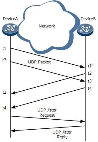
The NQA source (Device A) sends packets to the NQA destination (Device B) at a specified interval. Timestamp t1 is added when a packet is sent.
Upon receipt of the packet, the destination adds timestamp t1' to the packet.
After processing the packet, the destination adds timestamp t2' to the packet and forwards it back to the source.
Upon receipt of the packet, the source adds timestamp t2 to the packet. (Timestamps t3/t3' and t4/t4' are similar.)

In a UDP jitter test, the maximum number of packets to be sent each time is equal to the configured probe-count value and jitter-packetnum value.
The following indexes can be calculated based on the information received by the source to clearly reflect the network status:
Maximum, minimum, and average jitter of the packets from the source to the destination and from the destination to the source
Maximum one-way delay from the source to the destination or from the destination to the source
Related Concepts
RTT = (t2 – t1) - (t2'- t1')
If the RTT is longer than the specified timeout period, the network is congested and UDP packets will be counted as lost packets.
Packet loss rate = Number of lost UDP packets/Number of sent UDP packets (Number of lost UDP packets = Number of sent UDP packets – Number of received UDP packets).
A UDP jitter test can measure jitter either unidirectionally or bidirectionally:
Source-to-destination jitter = (t3' – t1') – (t3 – t1)
A larger absolute jitter value indicates poorer link quality, no matter whether the jitter value is positive or negative.
Destination-to-source jitter = (t4 – t2) – (t4' – t2')
A larger absolute jitter value indicates poorer link quality, no matter whether the jitter value is positive or negative.
In a UDP jitter test, you can set the number of packets to be sent consecutively in a single test instance to simulate a certain type of traffic. For example, configure the source to send 3,000 UDP packets every 20 ms to simulate G.711 traffic.
A UDP jitter test can also measure the packet loss rate unidirectionally. On the network shown in Figure 1, destination (Device B) collects statistics about received packets. After source (Device A) finds that the number of packets sent by itself is different from the number of packets received by itself, source (Device A) initiates a unidirectional packet loss query to learn the number of packets received by destination (Device B).
Packet Loss SD: Source-to-destination packet loss rate
Source-to-destination packet loss rate = Number of packets sent by source (Device A) – Number of packets received by Device B
Packet Loss DS: Destination-to-source packet loss rate
Destination-to-source packet loss rate = Number of packets received by destination (Device B) – Number of packets received by source (Device A)
If the source (Device A) does not receive any query packet, it records Packet Loss Unknown in the NQA structure table.
Hardware-based UDP Jitter Test
Reduces the interval at which packets are sent. The minimum interval is 10 ms.
Increases the number of concurrent test instances. To increase the number of concurrent test instances, install more line processing units on a device.
Increases the accuracy of the calculated delay and jitter time.
By default, UDP jitter (hardware-based) is not enabled. To implement a hardware-based UDP jitter test, enable the interface board to send packets.
Item |
UDP Jitter Test |
Hardware-based UDP Jitter Test |
|---|---|---|
Minimum interval at which test packets are sent |
20 ms |
10 ms |
Maximum number of concurrent test instances |
100 concurrent test instances on each device |
The number of concurrent test instances increases with the number of boards. |
Jitter calculation |
The main control board timestamps packets. |
Every interface board timestamps packets more precisely. |