Inter-AS VPLS
Definition
Inter-AS VPLS refers to VPLS applications across more than one AS. Inter-AS VPLS Option A, Option B, and Option C are supported.

Except the learning and forwarding functions of VSIs, the fundamentals and implementation of PW establishment in inter-AS VPLS are similar to those in inter-AS L2VPN.
Purpose
Inter-AS VPLS enables VPLS users in different ASs to communicate.
Implementation of Inter-AS VPLS Option A
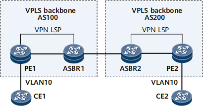
On the network shown in Figure 1, the implementation of inter-AS VPLS Option A is as follows:
An IGP is configured on the backbone network to allow communications between devices in the same AS.
MPLS is enabled on the backbone network and a dynamic LSP is established between the PE and ASBR in the same AS.
An IBGP peer relationship and a VPN LSP are established between the PE and ASBR in the same AS.
VSIs are configured on the PE and ASBR in the same AS, and the AC interfaces of the devices are bound to these VSIs. On an ASBR in an AS, configure its peer ASBR in the other AS as if it was a CE.
Implementation of Inter-AS VPLS Option B
According to the BGP VPLS standards, in Option B, when L2VPN A-D routes are transmitted between ASs, a new label block is allocated, and the mapping between the new label block and the original label block is created.
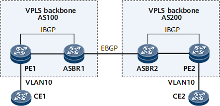
On the network shown in Figure 2, the implementation of inter-AS VPLS Option B is as follows:
Establish an EBGP peer relationship between ASBRs, configure an L2VPN-AD address family, and trigger the establishment of a local IFNET tunnel.
Establish an IBGP peer relationship between a PE and an ASBR in the same AS and configure VPN LSPs.
Configure BGP VPLS on the PEs on both ends, configure a VSI on a PE and an ASBR in the same AS, and bind the AC interface to the VSI of each device.
Implementation of Inter-AS VPLS Option C
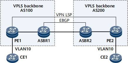
On the network shown in Figure 3, the implementation of inter-AS VPLS Option C is as follows:
Configure an IGP on the backbone network to allow communications between devices within the same AS.
Enable MPLS on the backbone network and establish a dynamic LSP between the PE and ASBR within the same AS.
Establish an IBGP peer relationship between the PE and ASBR within the same AS and an EBGP peer relationship between ASBRs.
Configure routing policies on ASBRs and enable the ASBRs to exchange labeled routes.
Establish an MP-EBGP peer relationship between PE1 and PE2.
Configure a VSI on each of PE1 and PE2 and bind the AC interface of each PE to a corresponding VSI.
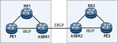
To improve scalability, you can specify a route reflector (RR) in each AS. The RR stores all L2VPN routes and exchanges L2VPN routing information with the PE within an AS.
Application Scenarios of Inter-AS VPLS Options
Inter-AS Option A: Its advantage is that configurations are easy. There is no need to run MPLS between ASBRs or perform particular configurations for inter-AS communications. The disadvantage of inter-AS Option A is that this mode has poor expansibility and poses high requirements for PEs. This mode is applicable to the early service deployment phase when the number of inter-AS VPNs is small.
- Inter-AS Option B: Its advantage is that ASBRs exchange information over routes, rather than along dedicated links. The disadvantage of inter-AS Option B is that label mappings need to be configured on ASBRs, and consequently, a great number of labels are consumed, leading to a label waste. In addition, an ASBR needs to establish an LSP with each PE in the same AS, which results in the shortage of label resources on the ASBR and easily leads to a performance bottleneck.
Inter-AS Option C: Its advantage is that ASBRs only forward packets but do not maintain VPN routes, and intermediate devices need to support only MPLS forwarding. This mode prevents the ASBRs from becoming performance bottlenecks. The disadvantage of this mode is that the management cost is high for maintaining an end-to-end BGP LSP. This mode is applicable when the number of inter-AS VPNs is large, many ASs are crossed, and services grow on a large scale.