Basic Concepts of IS-IS
IS-IS Areas

Level-1 device
A Level-1 device manages intra-area routing. It establishes neighbor relationships with only the Level-1 and Level-1-2 devices in the same area and maintains a Level-1 LSDB. The LSDB contains routing information in the local area. A packet to a destination beyond this area is forwarded to the nearest Level-1-2 device.
Level-2 device
A Level-2 device manages inter-area routing. It can establish neighbor relationships with all Level-2 devices and Level-1-2 devices, and maintains a Level-2 LSDB which contains inter-area routing information.
All Level-2 routers form the backbone network of the routing domain. They are responsible for communications between areas. The Level-2 routers in the routing domain must be in succession to ensure the continuity of the backbone network. Only Level-2 routers can directly exchange data packets or routing information with the routers beyond the area.
Level-1-2 device
A device, which can establish neighbor relationships with both Level-1 devices and Level-2 devices, is called a Level-1-2 device. A Level-1-2 device can establish Level-1 neighbor relationships with Level-1 devices and Level-1-2 devices in the same area. It can also establish Level-2 neighbor relationships with Level-2 devices and Level-1-2 devices in other areas. Level-1 devices can be connected to other areas only through Level-1-2 devices.
A Level-1-2 device maintains two LSDBs: a Level-1 LSDB and a Level-2 LSDB. The Level-1 LSDB is used for intra-area routing, whereas the Level-2 LSDB is used for inter-area routing.

Level-1 devices in different areas cannot establish neighbor relationships. Level-1-2 devices can establish neighbor relationships with each other, regardless of the areas to which they belong.
Interface level
A Level-1-2 device may need to establish only a Level-1 adjacency with one neighbor and establish only a Level-2 adjacency with another neighbor. In this case, you can set the level of an interface to control the setting of adjacencies on the interface. Specifically, only Level-1 adjacencies can be established on a Level-1 interface, and only Level-2 adjacencies can be established on a Level-2 interface.
Address Structure of IS-IS
In OSI, the NSAP is used to locate resources. The ISO adopts the address structure shown in Figure 2. An NSAP is composed of the Initial Domain Part (IDP) and the Domain Specific Part (DSP). IDP is the counterpart of network ID in an IP address, and DSP is the counterpart of the subnet number and host address in an IP address.
As defined by the ISO, the IDP consists of the Authority and Format Identifier (AFI) and Initial Domain Identifier (IDI). AFI specifies the address assignment mechanism and the address format; the IDI identifies a domain.
The DSP consists of the High Order DSP (HODSP), system ID, and NSAP Selector (SEL). The HODSP is used to divide areas; the system ID identifies a host; the SEL indicates the service type.
The lengths of the IDP and DSP are variable. The length of the NSAP varies from 8 bytes to 20 bytes.
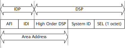
Area address
An IDP and HODSP of the DSP can identify a routing domain and the areas in a routing domain; therefore, the combination of the IDP and HODSP is referred to as an area address, equal to an area ID in OSPF. You are advised to avoid the situation where different Level-1 areas in the same routing domain have the same area address. The area addresses of routers in the same Level-1 area must be the same.
A router generally requires only one area address, and the area addresses of all nodes in the same area must be the same. An IS-IS process can be configured with a maximum of three area addresses to support seamless combination, division, and transformation of areas.
System ID
A system ID uniquely identifies a host or a router in an area. In the device, the length of the system ID is 48 bits (6 bytes).
A router ID corresponds to a system ID. If a router uses the IP address (192.168.1.1) of Loopback 0 as its router ID, its system ID used in IS-IS can be obtained through the following steps:
Extend each part of the IP address 192.168.1.1 to 3 digits and add 0 or 0s to the front of the part that is shorter than 3 digits.
Divide the extended address 192.168.001.001 into three parts, with each part consisting of 4 decimal digits.
The reconstructed 1921.6800.1001 is the system ID.
There are many ways to specify a system ID. Whichever you choose, ensure that the system ID uniquely identifies a host or a router.
If the same system ID is configured for more than one device on the same network, network flapping may occur. To address this problem, IS-IS provides the automatic recovery function. With the function, if the system detects an IS-IS system ID conflict, it automatically changes the local system ID to resolve the conflict. The first two bytes of the system ID automatically changed by the system are Fs, and the last four bytes are randomly generated. For example, FFFF:1234:5678 is such a system ID. If the conflict persists after the system automatically changes three system IDs, the system no longer resolves this conflict.
SEL
The role of an SEL (also referred to as NSAP Selector or N-SEL) is similar to that of the "protocol identifier" of IP. A transport protocol matches an SEL. The SEL is "00" in IP.
NET
A Network Entity Title (NET) indicates the network layer information of an IS itself and consists of an area ID and a system ID. It does not contain the transport layer information (SEL = 0). A NET can be regarded as a special NSAP. The length of the NET field is the same as that of an NSAP, varying from 8 bytes to 20 bytes. For example, in NET ab.cdef.1234.5678.9abc.00, the area is ab.cdef, the system ID is 1234.5678.9abc, and the SEL is 00.
In general, an IS-IS process is configured with only one NET. When areas need to be redefined, for example, areas need to be combined or an area needs to be divided into sub-areas, you can configure multiple NETs.
A maximum of three area addresses can be configured in an IS-IS process, and therefore, you can configure only a maximum of three NETs. When you configure multiple NETs, ensure that their system IDs are the same.
The routers in an area must have the same area address.
IS-IS Network Types
Broadcast network
Point-to-point (P2P) network