GMAC Ping/Trace
Generic MAC (GMAC) ping is an extension to 802.1ag MAC ping, and GMAC trace is an extension to 802.1ag MAC trace. Both GMAC ping and GMAC trace can monitor the connectivity, packet loss ratio, and delay on the link between any two devices on Layer 2 networks. A device does not need to be configured with attributes related to 802.1ag like a maintenance domain (MD) or a maintenance association (MA) to implement GMAC ping or GMAC trace. The two functions can be performed on any interfaces of two devices on an Ethernet network.
GMAC Ping Principles
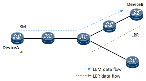
Figure 1 shows a network enabled with the GMAC ping function. This function has principles similar to those of 802.1ag MAC ping. The difference is that a source device does not need to be a maintenance association end point (MEP) and a destination device does not need to be a MEP or maintenance association intermediate point (MIP). In other words, GMAC ping can be implemented without the need to configure an MD, MA, or MEP on the source, intermediate, or destination device. The only requirement is to enable the GMAC ping function on the source and destination devices, whereas the intermediate devices have the bridge function to forward messages. GMAC ping can be applied to the network or part of the network on which an MD, MA, or MEP is not configured for locating connectivity faults.
Device A sends a loopback message (LBM) to Device B. In a VLAN scenario, the LBM must carry the host MAC address of Device B and the ID of the VLAN to which Device B belongs. In a VLL scenario, the message must carry the host MAC address of Device B and the ID of the L2VC to which Device B is bound. In a VSI scenario, the message must carry the host MAC address of Device B and the ID of the VSI to which Device B is bound.
After receiving the LBM, Device B responds to Device A with a loopback reply (LBR). Upon receiving the LBR, Device A calculates the difference between the time the LBM was sent and the time the LBR was received to analyze network performance.
GMAC Trace Principles
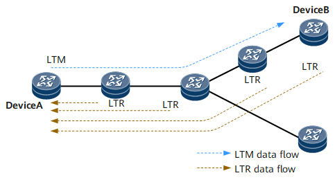
Figure 2 illustrates a network enabled with the GMAC trace function. This function has principles similar to those of 802.1ag MAC trace. The difference is that a source device does not need to be a MEP and a destination device does not need to be a MEP or MIP. In other words, GMAC trace can be implemented without the need to configure an MD, MA, or MEP on the source, intermediate, or destination device. The only requirement is to enable the GMAC trace function on the source, intermediate, and destination devices.
GMAC trace applies to a network or part of the network on which an MD, MA, or MEP is not configured to monitor forwarding paths and locate faulty nodes.
Device A sends a linktrace message (LTM) to Device B. In a VLAN scenario, the LTM must carry information about the host MAC address of Device B and the ID of the VLAN to which Device B belongs. In a VLL scenario, the message must carry the host MAC address of Device B and the ID of the L2VC to which Device B is bound. In a VSI scenario, the message must carry the host MAC address of Device B and the ID of the VSI to which Device B is bound.
After the LTM arrives at a device within the VLAN, the device reduces the TTL in the LTM by 1 and forwards the LTM if the TTL is not 0. If the TTL is zero, the device does not forward the LTM and replies with a linktrace reply (LTR). After the LTM reaches the destination Device B, Device B also replies with an LTR and does not forward the LTM.
After Device A receives the LTRs from all intermediate and destination devices, the process of monitoring the forwarding path is complete, and information about all nodes on the path between Device A and Device B is displayed.
Packet Processing
Different types of interfaces process packets differently in the GMAC ping and GMAC trace function, as shown in Table 1 and Table 2.
Type of the Inbound Interface |
Raw Encapsulation (Ethernet Encapsulation) |
Tagged Encapsulation (VLAN Encapsulation) |
|---|---|---|
VLANIF interface |
|
|
Ethernet main interface |
Tags are stripped. |
Reserves the tag, and no action is required. |
Dot1q sub-interface |
Strips one tag. |
Reserves the tag, and no action is required. |
Dot1q termination sub-interface |
Strips one tag. |
Reserves the tag, and no action is required. |
QinQ termination sub-interface (in symmetric mode) |
Strips the outer tag. |
Reserves the double tags, and no action is required. |
QinQ termination sub-interface (in asymmetric mode) |
Strips the double tags. |
Strips two tags and then adds one tag. |
Type of the Outbound Interface |
Raw Encapsulation (Ethernet Encapsulation) |
Tagged Encapsulation (VLAN Encapsulation) |
|---|---|---|
VLANIF interface |
|
|
Ethernet main interface |
A specific tag is added. |
The tag is replaced. |
Dot1q sub-interface |
Adds one tag. |
Replaces the tag with the tag that is encapsulated on the outbound interface. |
Dot1q termination sub-interface |
Adds one tag. |
Replaces the tag with the tag that is encapsulated on the outbound interface. |
QinQ termination sub-interface (in symmetric mode) |
Adds the outer tag. |
Replaces the outer tag with the tag that is encapsulated on the outbound interface. |
QinQ termination sub-interface (in asymmetric mode) |
Adds double tags. |
Removes the outer tag and then adds two tags that are encapsulated |