VLAN Communication Principles
Basic Principles
To improve frame processing efficiency, frames arriving at a switch must carry a VLAN tag for uniform processing. If an untagged frame enters a switch port which has a PVID configured, the port then add a VLAN tag whose VID is the same as the PVID to the frame. If a tagged frame enters a switch port that has a PVID configured, the port does not add any tag to the frame.
The switch processes frames in a different way according to the port types. The following table describes how a port processes a frame.
Principles of Intra-VLAN Communication Across Switches
Hosts of a VLAN are sometimes connected to different switches. In this situation, ports of different switches must be able to recognize and send packets belonging to this VLAN, and a trunk link is used.
A trunk link plays the following two roles:
Reply function
A trunk link can transparently transmit VLAN packets from a switch to another interconnected switch.
Backbone function
A trunk link can transmit multiple VLAN packets.
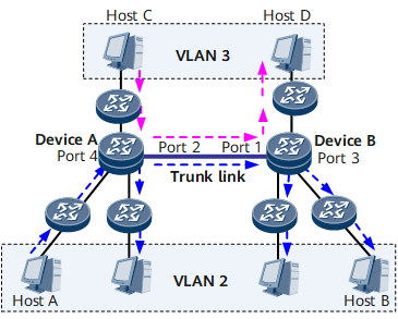
On the network shown in Figure 1, the trunk link between DeviceA and DeviceB must support both the intra-VLAN 2 communication and the intra-VLAN 3 communication. Therefore, the ports at both ends of the trunk link must be configured to be bound to VLAN 2 and VLAN 3. That is, Port 2 on DeviceA and Port 1 on DeviceB must belong to both VLAN 2 and VLAN 3.
Host A sends a frame to Host B in the following process:
The frame is first sent to Port 4 on A.
A tag is added to the frame on Port 4. The VID field of the tag is set to 2, that is, the ID of the VLAN to which Port 4 belongs.
- Device A checks whether its MAC address table contains the MAC address destined for Host B.
- If so, Device A sends the frame to the outbound interface Port 2.
- If not, Device A sends the frame to all interfaces bound to VLAN 2 except for Port 4.
Upon receipt of the frame, Port 2 sends the frame to DeviceB.
- After receiving the frame, Device B checks whether its MAC address table contains the MAC address destined for Host B.
- If so, Device B sends the frame to the outbound interface Port 3.
- If not, Device B sends the frame to all interfaces bound to VLAN 2 except for Port 1.
Upon receipt of the frame, Port 3 sends the frame to Host B.
The intra-VLAN 3 communication is similar, and is omitted here.
Inter-VLAN Communication Principles
After VLANs are configured, hosts in different VLANs cannot directly communicate with each other at Layer 2. To implement the communication between VLANs, you need to create routes between VLANs. The specific implementation schemes are as follows:
Layer 2 switch + router
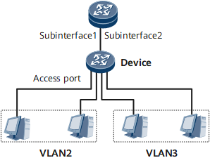
On the network shown in Figure 2, a switched Ethernet interface on a Layer 2 switch is connected to a routed Ethernet interface on a router for LAN communication.
If VLAN 2 and VLAN 3 are configured on the switch, to enable VLAN 2 to communicate with VLAN 3, you need to perform the following operations: create two sub-interfaces on the routed Ethernet interface that is connected to the switch. Sub-interface 1 is used to forward traffic to VLAN 2, and sub-interface 2 is used to forward traffic to VLAN 3.
Then, configure 802.1Q encapsulation on and assign IP addresses to the sub-interfaces.
On the switch, you need to configure the switched Ethernet port to a Trunk or Hybrid interface and allow frames of VLAN 2 and VLAN 3 to pass.
The defects of the Layer 2 switch + Router mode are as follows:Multiple devices are needed, and the networking is complex.
A router is deployed, which is expensive and provides a low transmission rate.
Layer 3 switch
Layer 3 switching combines both routing and switching techniques to implement routing on a switch, improving the overall performance of the network. After sending the first data flow based on a routing table, a Layer 3 switch generates a mapping table, in which the mapping between the MAC address and the IP address about this data flow is recorded. If the switch needs to send the same data flow again, it directly sends the data flow at Layer 2 but not Layer 3 based on the mapping table. In this manner, delays on the network caused by route selection are eliminated, and data forwarding efficiency is improved.
To allow the first data flow to be correctly forwarded based on the routing table, the routing table must contain correct routing entries. Therefore, configuring a Layer 3 interface and a routing protocol on the Layer 3 switch is required. VLANIF interfaces are therefore introduced.
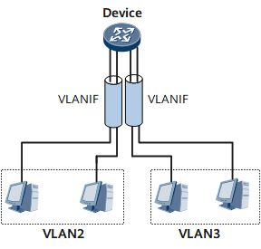
A VLANIF interface is a Layer 3 logical interface, which can be configured on either a Layer 3 switch or a router.
As shown in Figure 3, VLAN 2 and VLAN 3 are configured on the switch. You can then create two VLANIF interfaces on the switch and assign IP addresses to and configure routes for them. In this manner, VLAN 2 can communicate with VLAN 3.
The Layer 3 switching offsets the defects in the scheme of Layer 2 switch + Router, and can implement faster traffic forwarding at a lower cost. Nevertheless, the Layer 3 switching has the following defects:The Layer 3 switching is applicable only to a network whose interfaces are almost all Ethernet interfaces.
The Layer 3 switching is applicable only to a network with stable routes and few changes in the network topology.

- A PC does not need to know the VLAN to which it belongs. It sends only untagged frames.
- After receiving an untagged frame from a PC, a switching device determines the VLAN to which the frame belongs. The determination is based on the configured VLAN division method such as port information, and then the switching device processes the frame accordingly.
- If the frame needs to be forwarded to another switching device, the frame must be transparently transmitted along a trunk link. Frames transmitted along trunk links must carry VLAN tags to allow other switching devices to properly forward the frame based on the VLAN information.
- Before sending the frame to the destination PC, the switching device connected to the destination PC removes the VLAN tag from the frame to ensure that the PC receives an untagged frame.
Generally, only tagged frames are transmitted on trunk links; only untagged frames are transmitted on access links. In this manner, switching devices on the network can properly process VLAN information and PCs are not concerned about VLAN information.