Basic Concepts
MSTP Network Hierarchy
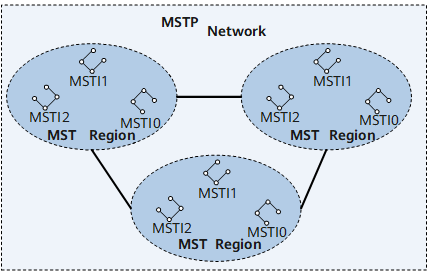
As shown in Figure 1, the Multiple Spanning Tree Protocol (MSTP) network consists of one or more Multiple Spanning Tree (MST) regions. Each MST region contains one or more Multiple Spanning Tree Instances (MSTIs). An MSTI is a tree network consisting of devices running STP, Rapid Spanning Tree Protocol (RSTP), or MSTP.
MST Region
- MSTP-enabled
- Same region name
- Same VLAN-MSTI mappings
- Same MSTP revision level
A LAN can comprise several MST regions that are directly or indirectly connected. Multiple devices can be grouped into an MST region by using MSTP configuration commands.
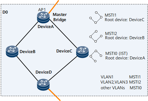
As shown in Figure 2, the MST region D0 contains Device A, Device B, Device C, and Device D, and has three MSTIs.
VLAN Mapping Table
The VLAN mapping table is an attribute of the MST region. It describes mappings between VLANs and MSTIs.
- VLAN 1 is mapped to MSTI 1.
- VLAN 2 and VLAN 3 are mapped to MSTI 2.
- Other VLANs are mapped to MSTI 0.
Regional Root
Regional roots are classified as Internal Spanning Tree (IST) and MSTI regional roots.
In the region B0, C0, and D0 on the network shown in Figure 4, the devices closest to the Common and Internal Spanning Tree (CIST) root are IST regional roots.
An MST region can contain multiple spanning trees, each called an MSTI. An MSTI regional root is the root of the MSTI. On the network shown in Figure 3, each MSTI has its own regional root.
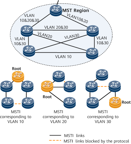
MSTIs are independent of each other. An MSTI can correspond to one or more VLANs, but a VLAN can be mapped to only one MSTI.
Master Bridge
The master bridge is the IST master, which is the device closest to the CIST root in a region, for example, Device A shown in Figure 2.
If the CIST root is in an MST region, the CIST root is the master bridge of the region.
CIST Root
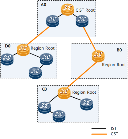
On the network shown in Figure 4, the CIST root is the root bridge of the CIST. The CIST root is a device in A0.
CST
A Common Spanning Tree (CST) connects all the MST regions on a switching network.
If each MST region is considered a node, the CST is calculated by using STP or RSTP based on all the nodes.
As shown in Figure 4, the MST regions are connected to form a CST.
IST
An IST resides within an MST region.
An IST is a special MSTI with the MSTI ID being 0, called MSTI 0.
An IST is a segment of the CIST in an MST region.
As shown in Figure 4, the devices in an MST region are connected to form an IST.
CIST
A CIST, calculated by using STP or RSTP, connects all the devices on a switching network.
As shown in Figure 4, the ISTs and the CST form a complete spanning tree, the CIST.
SST
- A device running STP or RSTP belongs to only one spanning tree.
- An MST region has only one device.
As shown in Figure 4, the device in B0 forms an SST.
Port Role
Based on RSTP, MSTP has two additional port types. MSTP ports can be root ports, designated ports, alternate ports, backup ports, edge ports, master ports, and regional edge port.
The functions of root ports, designated ports, alternate ports, and backup ports have been defined in RSTP. Table 1 lists all port roles in MSTP.

Except edge ports, all ports participate in MSTP calculation.
A port can play different roles in different spanning tree instances.
Port Role |
Description |
|---|---|
Root port |
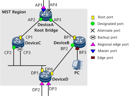
A root port is the non-root bridge port closest to the root bridge. Root bridges do not have root ports. Root ports are responsible for sending data to root bridges. As shown in Figure 5, Device A is the root; CP1 is the root port on Device C; BP1 is the root port on Device B. |
Designated port |
The designated port on a device forwards BPDUs to the downstream device. As shown in Figure 5, AP2 and AP3 are designated ports on Device A; CP2 is a designated port on Device C. |
Alternate port |
As shown in Figure 5, BP2 is an alternate port. |
Backup port |
As shown in Figure 5, CP3 is a backup port. |
Master port |
A master port is on the shortest path connecting MST regions to the CIST root. BPDUs of an MST region are sent to the CIST root through the master port. Master ports are special regional edge ports, functioning as root ports on ISTs or CISTs and master ports in instances. As shown in Figure 5, Device A, Device B, Device C, and Device D form an MST region. AP1 on Device A, being the nearest port in the region to the CIST root, is the master port. |
Regional edge port |
A regional edge port is located at the edge of an MST region and connects to another MST region or an SST. During MSTP calculation, the roles of a regional edge port in the MSTI and the CIST instance are the same. If the regional edge port is the master port in the CIST instance, it is the master port in all the MSTIs in the region. As shown in Figure 5, AP1, DP1, and DP2 in an MST region are directly connected to other regions, and therefore they are all regional edge ports of the MST region. AP1 is a master port in the CIST. Therefore, AP1 is the master port in every MSTI in the MST region. |
Edge port |
An edge port is located at the edge of an MST region and does not connect to any device. Generally, edge ports are directly connected to terminals. After MSTP is enabled on a port, edge-port detecting is started automatically. If the port fails to receive BPDU packets within seconds, the port is set to an edge port. Otherwise, the port is set to a non-edge port. As shown in Figure 5, BP3 is an edge port. |
MSTP Port Status
Table 2 lists the MSTP port status, which is the same as the RSTP port status.
Port Status |
Description |
|---|---|
Forwarding |
A port in the Forwarding state can send and receive BPDUs as well as forward user traffic. |
Learning |
This is a transition stage. A port in the Learning state learns MAC addresses from user traffic to construct a MAC address table. In the Learning state, the port can send and receive BPDUs, but not forward user traffic. |
Discarding |
A port in the Discarding state can only receive BPDUs. |
There is no necessary link between the port status and the port role. Table 3 lists the relationships between port roles and port status.
Port Status |
Root Port/Master Port |
Designated Port |
Regional Edge Port |
Alternate Port |
Backup Port |
|---|---|---|---|---|---|
Forwarding |
Yes |
Yes |
Yes |
No |
No |
Learning |
Yes |
Yes |
Yes |
No |
No |
Discarding |
Yes |
Yes |
Yes |
Yes |
Yes |
Yes: The port supports this status.
No: The port does not support this status.