MST BPDUs
Multiple Spanning Tree Protocol (MSTP) calculates spanning trees on the basis of Multiple Spanning Tree Bridge Protocol Data Units (MST BPDUs). By transmitting MST BPDUs, spanning tree topologies are computed, network topologies are maintained, and topology changes are conveyed.
Table 1 shows differences between Topology Change Notification (TCN) BPDUs, configuration BPDUs defined by STP, Rapid Spanning Tree (RST) BPDUs defined by Rapid Spanning Tree Protocol (RSTP), and MST BPDUs defined by MSTP.
Version |
Type |
Name |
|---|---|---|
0 |
0x00 |
Configuration BPDU |
0 |
0x80 |
TCN BPDU |
2 |
0x02 |
RST BPDU |
3 |
0x02 |
MST BPDU |
MST BPDU Format
Figure 1 shows the MST BPDU format.
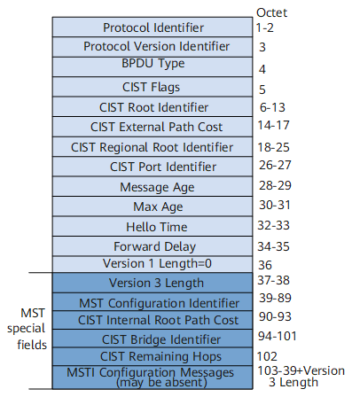
The first 36 bytes of an intra-region or inter-region MST BPDU are the same as those of an RST BPDU.
Fields from the 37th byte of an MST BPDU are MSTP-specific. The field MSTI Configuration Messages consists of configuration messages of multiple MSTIs.
Table 2 lists the major information carried in an MST BPDU.
Field |
Byte |
Description |
|---|---|---|
Protocol Identifier |
2 |
Indicates the protocol identifier. |
Protocol Version Identifier |
1 |
Indicates the protocol version identifier. 0 indicates STP; 2 indicates RSTP; 3 indicates MSTP. |
BPDU Type |
1 |
Indicates the BPDU type:
|
CIST Flags |
1 |
Indicates the Common and Internal Spanning Tree (CIST) flags. |
CIST Root Identifier |
8 |
Indicates the CIST root switching device ID. |
CIST External Path Cost |
4 |
Indicates the total path costs from the MST region where the switching device resides to the MST region where the CIST root switching device resides. This value is calculated based on link bandwidth. |
CIST Regional Root Identifier |
8 |
Indicates the ID of the regional root switching device on the CIST, that is, the Internal Spanning Tree (IST) master ID. If the root is in this region, the CIST Regional Root Identifier is the same as the CIST Root Identifier. |
CIST Port Identifier |
2 |
Indicates the ID of the designated port in the IST. |
Message Age |
2 |
Indicates the lifecycle of the BPDU. |
Max Age |
2 |
Indicates the maximum lifecycle of the BPDU. If the Max Age timer expires, it is considered that the link to the root fails. |
Hello Time |
2 |
Indicates the Hello timer value. |
Forward Delay |
2 |
Indicates the forwarding delay timer. |
Version 1 Length |
1 |
Indicates the BPDUv1 length, which is fixed to 0. |
Version 3 Length |
2 |
Indicates the BPDUv3 length. |
MST Configuration Identifier |
51 |
Indicates the MST regional label information, which includes four fields shown in Figure 2. Interconnected switching devices that are configured with the same MST configuration identifier belong to one region. For details about these four fields, see Table 3. |
CIST Internal Root Path Cost |
4 |
Indicates the total path costs from the local port to the IST master. This value is calculated based on link bandwidth. |
CIST Bridge Identifier |
8 |
Indicates the ID of the designated switching device on the CIST. |
CIST Remaining Hops |
1 |
Indicates the remaining hops of the BPDU in the CIST. |
MSTI Configuration Messages (may be absent) |
16 |
Indicates the Multiple Spanning Tree Instances (MSTI) configuration information. Each MSTI configuration message uses 16 bytes, and therefore this field has N x 16 bytes in the case of N MSTIs. Figure 3 shows the structure of a single MSTI configuration message. Table 3 describes every sub-field. |
Figure 2 shows the sub-fields in the MST Configuration Identifier field.
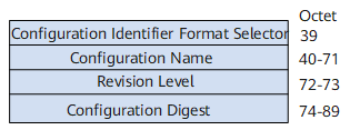
Table 3 describes the sub-fields in the MST Configuration Identifier field.
Sub-field |
Byte |
Description |
|---|---|---|
Configuration Identifier Format Selector |
1 |
The value is 0. |
Configuration Name |
32 |
Indicates the regional name. The value is a 32-byte string. |
Revision Level |
2 |
The value is a 2-byte non-negative integer. |
Configuration Digest |
16 |
Indicates a 16-byte digest obtained by encrypting the mappings between VLANs and instances in the region based on the HMAC-MD5 algorithm. |
Figure 3 shows the sub-fields in the MST Configuration Messages field.
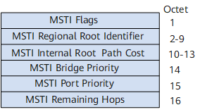
Table 4 describes the sub-fields in the MSTI Configuration Messages field.
Sub-field |
Byte |
Description |
|---|---|---|
MSTI Flags |
1 |
Indicates the MSTI flags. |
MSTI Regional Root Identifier |
8 |
Indicates the MSTI regional root switching device ID. |
MSTI Internal Root Path Cost |
4 |
Indicates the total path costs from the local port to the MSTI regional root switching device. This value is calculated based on link bandwidth. |
MSTI Bridge Priority |
1 |
Indicates the priority value of the designated switching device in the MSTI. |
MSTI Port Priority |
1 |
Indicates the priority value of the designated port in the MSTI. |
MSTI Remaining Hops |
1 |
Indicates the remaining hops of the BPDU in the MSTI. |
Configurable MST BPDU Format
Currently, there are two MST BPDU formats:
dot1s: BPDU format defined in IEEE 802.1s.
legacy: private BPDU format.
If a port transmits either dot1s or legacy BPDUs by default, the user needs to identify the format of BPDUs sent by the peer, and then runs a command to configure the port to support the peer BPDU format. Once the configuration is incorrect, a loop probably occurs due to incorrect MSTP calculation.
By using the stp compliance command, you can configure a port on a Huawei datacom device to automatically adjust the MST BPDU format. With this function, the port automatically adopts the peer BPDU format. The following MST BPDU formats are supported by Huawei datacom devices:
auto
dot1s
legacy
In addition to dot1s and legacy formats, the auto mode allows a port to automatically switch to the BPDU format used by the peer based on BPDUs received from the peer. In this manner, the two ports use the same BPDU format. In auto mode, a port uses the dot1s BPDU format by default, and keeps pace with the peer after receiving BPDUs from the peer.
Configurable Maximum Number of BPDUs Sent by a Port at a Hello Interval
BPDUs are sent at Hello intervals to maintain the spanning tree. If a switching device does not receive any BPDU during a certain period of time, the spanning tree will be re-calculated.
After a switching device becomes the root, it sends BPDUs at Hello intervals. Non-root switching devices adopt the Hello Time value set for the root.
Huawei datacom devices allow the maximum number of BPDUs sent by a port at a Hello interval to be configured as needed.
The greater the configured value, the more BPDUs can be sent at a Hello interval. Configuring the maximum number to a proper value limits the number of BPDUs that can be sent by a port at a Hello interval. This helps prevent network topology flapping and avoid excessive use of bandwidth resources by BPDUs.