VPLS PW Ping/Trace Test
Background
As a main technology for setting up a metropolitan area network (MAN), virtual private LAN service (VPLS) has been widely applied globally. VPLS, however, is poor in terms of service management and monitoring. In this case, an optimized VPLS OAM mechanism is required.
On a VPLS network, the performance of PWs affects the entire network performance. For example, the connectivity of PWs determines whether traffic can be normally forwarded between users, and the forwarding performance of PWs determines whether the forwarding capacity of the network complies with the Service Level Agreement (SLA) signed with users. To monitor PWs on the VPLS network, VPLS PW ping and VPLS PW trace are developed for detecting the connectivity of PWs, collecting performance information about PWs, discovering packet forwarding paths along PWs, and locating faults on PWs.
VPLS PW ping or VPLS PW trace operations initiated through NQA commands are the same as ping or trace operations initiated through common command lines in principle, and additionally provide the scheduling and result collection mechanism and the threshold-exceeding alarm function.
VPLS PW ping and VPLS PW trace comply with standard protocols in implementing PW detection: MPLS echo packets that carry Forwarding Equivalence Class (FEC) fields are encapsulated in tunnel mode and labeled with the Router Alert option; the Router Alert function is enabled on the VPLS network. MPLS echo packets are transmitted between PEs to detect PWs and are not sent to CEs, which means that the NQA test instance can be configured only on PEs. If an NQA test instance is configured on a non-PE device, it cannot be started because there is no VSI used for establishing PWs on the non-PE device and as a result, the test result is "drop."
- A VPLS PW ping or VPLS PW trace test instance can be configured to actively monitor VPLS services and detect faults in VPLS services. In the case that the round-trip time (RTT) of a packet exceeds the threshold, a connection is interrupted, or the response to a request packet times out, an SNMP trap message in an NQA test instance is sent to the Network Management System (NMS) for notification and collects the statistics (such as the RTT) for users to query.
- The scheduling function can be enabled to periodically schedule an NQA test instance to detect a specific VPLS PW as required. When multiple NQA test instances are started concurrently to detect multiple PWs, the scheduling function enables these NQA test instances to operate separately and arranges the operation time properly so that as many test instances as possible can be started for PW detection. The maximum number of test instances that the system allows is calculated based on the traffic metric of test instances.
Implementation
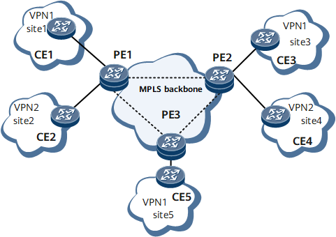
- PE1 initiates a VPLS PW ping test instance after the virtual switch instance (VSI) and peer IP address are configured on PE1. Then, the NQA module constructs an MPLS Echo Request message carrying the Router Alert option and sends it over the public network based on the forwarding information in the forwarding table.
- Upon receipt, PE2 parses the packet and determines whether it is the destination of the packet. If the destination address is PE2's address, PE2 sends the MPLS Echo Request packet to the CPU for processing. Then, it constructs an MPLS Echo Reply packet carrying timestamps indicating the time when the MPLS Echo Request message was received and when the MPLS Echo Reply message was sent. Then PE2 sends the Echo Reply message to PE1.
- When the MPLS Echo Reply message reaches PE1, PE1 saves the time information in the message to the test result table. Based on the time information, PE1 calculates the unidirectional delay of the message transmission after the transmit and receive ends have synchronized their clocks. If PE1 does not receive an Echo Reply message after the timeout period relapses, it records an error in the test result table.
- PE1 initiates a VPLS PW trace test instance after the VSI and peer IP address are configured on PE1. Then, the NQA module constructs an MPLS Echo Request message in which the Router Alert option is encapsulated and a timestamp is added to the private TLV, and sends it over the public network based on the forwarding information in the forwarding table. The TTL value in the first MPLS Echo Request message is 1 by default, and you can specify an initial TTL value and the maximum TTL value.
- Upon receipt, the transit node forwards the MPLS Echo Request message to the next hop when the TTL of the message times out. The transit node obtains next-hop information based on the incoming label and inbound interface index, and encapsulates the DS TLV in an MPLS Echo Reply message. Then the transit node sends the MPLS Echo Reply message to PE1.
- Upon receipt, PE1 increases the TTL value by 1 and constructs another MPLS Echo Request message for transmission until the message reaches the destination or the TTL reaches the maximum value.