OSPF IP FRR
OSPF IP fast reroute (FRR) refers to the process by which OSPF precomputes a backup path based on the network-wide LSDBs, and stores this backup path in the forwarding table. If the primary path fails, traffic can be quickly switched to the backup path.
Background
As networks develop, voice over IP (VoIP) and online video services pose higher requirements for real-time transmission. Nevertheless, if a primary link fails, OSPF-enabled devices need to perform multiple operations, including detecting the fault, updating the link-state advertisement (LSA), flooding the LSA, calculating routes, and delivering forward information base (FIB) entries before switching traffic to a new link. This process takes a much longer time, the minimum delay to which users are sensitive. As a result, the requirements for real-time transmission cannot be met. OSPF IP FRR can solve this problem. OSPF IP FRR conforms to dynamic IP FRR defined by standard protocols. With OSPF IP FRR, devices can switch traffic from a faulty primary link to a backup link, protecting against a link or node failure.
Major FRR techniques include loop-free alternate (LFA), U-turn, Not-Via, Remote LFA, and MRT, among which OSPF supports only LFA and Remote LFA.
Related Concepts
OSPF IP FRR
OSPF IP FRR refers to a mechanism in which a device uses the loop-free alternate (LFA) algorithm to compute the next hop of a backup link and stores the next hop together with the primary link in the forwarding table. If the primary link fails, the device switches the traffic to the backup link before routes are converged on the control plane. This mechanism keeps the traffic interruption duration and minimizes the impacts.
OSPF IP FRR policy
An OSPF IP FRR policy can be configured to filter alternate next hops. Only the alternate next hops that match the filtering rules of the policy can be added to the IP routing table.
LFA algorithm
A device uses the shortest path first (SPF) algorithm to calculate the shortest path from each neighbor with a backup link to the destination node. The device then uses the inequalities defined in standard protocols and the LFA algorithm to calculate the next hop of the loop-free backup link that has the smallest cost of the available shortest paths.
Remote LFA
LFA FRR cannot be used to calculate alternate links on large-scale networks, especially on ring networks. Remote LFA FRR addresses this problem by calculating a PQ node and establishing a tunnel between the source node of a primary link and the PQ node. If the primary link fails, traffic can be automatically switched to the tunnel, which improves network reliability.
P space
Remote LFA uses the source end of a protection link as the root node and calculates an SPT to all the other nodes on the network (with the protection link calculated in the tree). Then Remote LFA removes all the nodes along the protection link from the SPT, and the set of the remaining nodes is called a P space.
Extended P space
Remote LFA uses neighbors of the source end of a protection link as root nodes and calculates separate SPTs (with the protection link calculated in the trees). Then Remote LFA removes all the nodes along the protection link from each SPT, and the set of the remaining nodes on the SPTs is called an extended P space.
Q space
Remote LFA uses the destination end of a protection link as the root node and calculates an SPT to all the other nodes on the network (with the protection link calculated in the tree). Then Remote LFA removes all the nodes along the protection link from the SPT, and the set of the remaining nodes is called a Q space.
PQ node
A PQ node exists both in the extended P space and Q space and is used by Remote LFA as the destination of a protection tunnel.
OSPF LFA FRR
OSPF LFA FRR protects traffic against either a link failure or a node-and-link failure. The node-and-link protection takes precedence over the link protection.
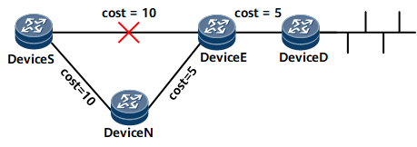
Link protection
Link protection takes effect when the traffic to be protected flows along a specified link.
In Figure 1, traffic flows from Device S to Device D. The primary link is Device S->Device E->Device D, and the backup link is Device S->Device N->Device E->Device D. If link costs meet the inequality: Distance_opt(N, D) < Distance_opt(N, S) + Distance_opt(S, D) and OSPF IP FRR is enabled, Device S switches the traffic to the backup link if the primary link fails, reducing the traffic interruption duration.

Distance_opt(X, Y) indicates the shortest link from X to Y. S stands for a source node, E for the faulty node, N for a node along a backup link, and D for a destination node.
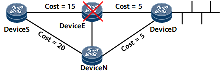
Node-and-link protection
Node-and-link protection takes effect when the traffic to be protected.
In Figure 2, traffic flows from Device S to Device D. The primary link is Device S->Device E->Device D, and the backup link is Device S->Device N->Device D. With OSPF IP FRR, Device S switches the traffic to the backup link if the primary link fails, reducing the traffic interruption duration.
Node-and-link protection takes effect when the following conditions are met:
- The link costs meet the inequality: Distance_opt(N, D) < Distance_opt(N, S) + Distance_opt(S, D).
- The interface costs meet the inequality: Distance_opt(N, D) < Distance_opt(N, E) + Distance_opt(E, D).
Distance_opt(X, Y) indicates the shortest link from X to Y. S stands for a source node, E for the faulty node, N for a node along a backup link, and D for a destination node.
OSPF Remote LFA FRR
Similar to OSPF LFA FRR, remote LFA is also classified as link protection or node-and-link protection. The following example shows how remote LFA works to protect against link failures:
In Figure 3, traffic flows through PE1 -> P1 -> P2 -> PE2, and the primary link is between P1 and P2. Remote LFA calculates a PQ node (P4) and establishes a Label Distribution Protocol (LDP) tunnel between P1 and P4. If P1 detects a failure on the primary link, P1 encapsulates packets into MPLS packets and forwards the MPLS packets to P4. After receiving the packets, P4 removes the MPLS label from them and searches the IP routing table for a next hop to forward the packets to PE2. Remote LFA ensures uninterrupted traffic forwarding.
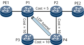
Calculates an SPT with each of P1's neighbors (excluding the neighbor on the protection link) as the root. In this case, neighbors PE1 and P3 are used for calculation. For each SPT, an extended P space is composed of the root node and those reachable nodes that belong to the SPT but do not pass through the P1→P2 link. When PE1 is used as a root node for calculation, the extended P space {PE1, P1, P3} is obtained. When P3 is used as a root node for calculation, the extended P space {PE1, P1, P3, P4} is obtained. By combining these two extended P spaces, the final extended P space {PE1, P1, P3, P4} is obtained.
Calculates a reverse SPT with P2 as the root. The obtained Q space is {P2, PE2, P4}.
Selects the PQ node (P4) that exists both in the extended P space and Q space.
On a network with a large number of nodes, to ensure that RLFA/TI-LFA calculation can be completed as soon as possible, the elected P and Q nodes may not be optimal, but they comply with rules. This does not affect the protection effect.
OSPF microloop avoidance
In Figure 3, OSPF remote LFA FRR is enabled, the primary link is PE1 -> P1 -> P2 -> PE2, and the backup link is PE1 -> P1 -> P3 -> P4 -> P2 -> PE2, and the link P1 -> P3 -> P4 is an LDP tunnel. If the primary link fails, traffic is switched to the backup link, and then another round of the new primary link calculation begins. Specifically, after P1 completes route convergence, its next hop becomes P3. However, the route convergence on P3 is slower than that on P1, and P3's next hop is still P1. As a result, a temporary loop occurs between P1 and P3. OSPF microloop avoidance can address this problem by delaying P1 from switching its next hop until the next hop of P3 becomes P4. Then traffic is switched to the new primary link (PE1 -> P1 -> P3 -> P4 -> P2 -> PE2), and on the link P1 -> P3 -> P4, traffic is forwarded based on IP routes.
OSPF microloop avoidance applies only to OSPF remote LFA FRR.
OSPF FRR in the Scenario Where Multiple Nodes Advertise the Same Route
Both OSPF LFA FRR and OSPF remote LFA FRR use the SPF algorithm to calculate the shortest path from each neighbor (root node) that provides a backup link to the destination node and store the node-based backup next hop, which applies to single-node routing scenarios. As networks are increasingly diversified, two ABRs or ASBRs are deployed to improve network reliability. In this case, OSPF FRR in a scenario where multiple nodes advertise the same route is needed.
In a scenario where multiple nodes advertise the same route (multi-node routing scenario), OSPF FRR is implemented by calculating the Type 3 LSAs advertised by ABRs of an area for intra-area, inter-area, ASE, or NSSA routing. Therefore, the OSPF FRR calculation methods are the same when multiple nodes advertise the same route. Inter-area routing is used as an example to describe how FRR in a multi-node routing scenario works.
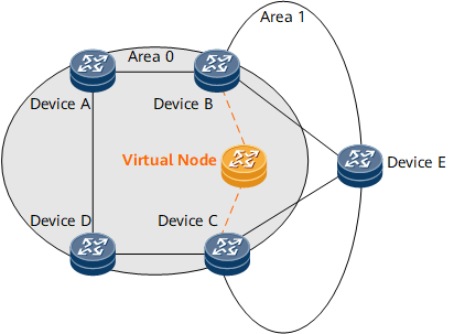
In Figure 4, Device B and Device C function as ABRs to forward routes between area 0 and area 1. Device E advertises an intra-area route. Upon receipt of the route, Device B and Device C translate it into a Type 3 LSA and flood the LSA to area 0. After OSPF FRR is enabled on Device A, Device A considers both Device B and Device C as its neighbors. Without a fixed neighbor as the root node, Device A fails to calculate the FRR backup next hop. To address this problem, a virtual node is simulated between Device B and Device C and used as the root node of Device A, and Device A uses the LFA or remote LFA algorithm to calculate the backup next hop. This solution converts multi-node routing into single-node routing.
For example, both Device B and Device C advertise the route 10.1.1.0/24, and OSPF FRR is enabled on Device A. After Device A receives the route, it fails to calculate a backup next hop for the route due to a lack of a fixed root node. To address this problem, a virtual node is simulated between Device B and Device C based on the two sources of the route 10.1.1.0/24. The virtual node forms a link with each of Device B and Device C. If the virtual node advertises a 10.1.1.0/24 route, it will use the smaller cost of the routes advertised by Device B and Device C as the cost of the route. If the cost of the route advertised by Device B is 5 and that of the route advertised by Device C is 10, the cost of the route advertised by the virtual node is 5. The cost of the link from Device B to the virtual node is 0, and that of the link from Device C to the virtual node is 5. The costs of the links from the virtual node to Device B and Device C are both 65535, the maximum value. Device A is configured to consider Device B and Device C as invalid sources of the 10.1.1.0/24 route and use the LFA or remote LFA algorithm to calculate the backup next hop for the route, with the virtual node as the root node.
In a scenario where multiple nodes advertise the same route, OSPF FRR can use the LFA or remote LFA algorithm. When OSPF FRR uses the remote LFA algorithm, PQ node selection has the following restrictions:
- An LDP LSP will be established by remote LFA between a faulty node and a PQ node, and a virtual node in a multi-node routing scenario cannot transmit traffic through LDP LSPs. As a result, the virtual node cannot be selected as a PQ node.
- The destination node is not used as a PQ node. After a virtual node is added to a multi-node routing scenario, the destination node becomes the virtual node. As a result, the nodes directly connected to the virtual node cannot be selected as PQ nodes.
OSPF SRLG FRR
A shared risk link group (SRLG) is a set of links that share a common physical resource (such as a fiber). These links share the same risk level. If one of the links fails, all the other links in the SRLG may also fail.
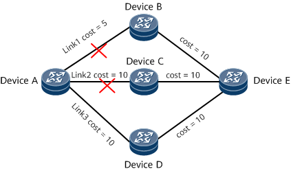
On the network shown in Figure 5, traffic is forwarded from Device A to Device E. There are three links between Device A and Device E: Link1, Link2, and Link3. The cost of Link1 is the smallest, and the costs of Link2 and Link3 are the same. Therefore, Link1 is the primary link for traffic forwarding.
- If Link1 fails but the backup link (Link2) is normal, traffic can be forwarded normally after being switched to the backup link.
- If both Link1 and Link2 fail, traffic is interrupted after being switched to the backup link.
OSPF SRLG FRR can be configured in the scenario where some links have the same risk of failure. If Link1 and Link2 have the same risk of failure, you can add them to an SRLG and configure OSPF SRLG FRR so that a link outside the SRLG is preferentially selected as a backup link, which reduces the possibility of service interruptions. After Link1 and Link2 are added to the same SRLG, OSPF LFA IP FRR selects Link3, which is not in the SRLG, as the backup link to provide protection for Link1. If both Link1 and Link2 fail, traffic can be switched to Link3 for normal transmission.
Derivative Functions
If you bind a Bidirectional Forwarding Detection (BFD) session with OSPF IP FRR, the BFD session goes down if BFD detects a link fault. If the BFD session goes down, OSPF IP FRR is triggered to switch traffic from the faulty link to the backup link, which minimizes the loss of traffic.