OSPF Multi-Area Adjacency
Background
In OSPF, intra-area links take precedence over inter-area links during route selection even when the inter-area links are shorter than the intra-area links. Each OSPF interface belongs to only one area. As a result, even when a high-speed link exists in an area, traffic of another area cannot be forwarded along the link. A common method used to solve this problem is to configure multiple sub-interfaces and add them to different areas. However, this method has a defect that an independent IP address needs to be configured for each sub-interface and then is advertised, which increases the total number of routes. In this situation, OSPF multi-area adjacency is introduced.
OSPF multi-area adjacency allows an OSPF interface to be multiplexed by multiple areas so that a link can be shared by the areas.
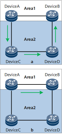
In Figure 1, the link between Device A and Device B in area 1 is a high-speed link.
In Figure 1 a, OSPF multi-area adjacency is disabled on Device A and Device B, and traffic from Device A to Device B in area 2 is forwarded along the low-speed link of Device A -> Device C -> Device D -> Device B.
In Figure 1 b, OSPF multi-area adjacency is enabled on Device A and Device B, and their multi-area adjacency interfaces belong to area 2. In this case, traffic from Device A to Device B in area 2 is forwarded along the high-speed link of Device A -> Device B.
- Allows interface multiplexing, which reduces OSPF interface resource usage in multi-area scenarios.
- Allows link multiplexing, which prevents a traffic detour to low-speed links and optimizes the OSPF network.
Related Concepts
Multi-area adjacency interface: indicates the OSPF logical interface created when OSPF multi-area adjacency is enabled on an OSPF-capable interface (main OSPF interface). The multi-area adjacency interface is also referred to as a secondary OSPF interface. The multi-area adjacency interface has the following characteristics:
- The multi-area adjacency interface and the main OSPF interface belong to different OSPF areas.
- The network type of the multi-area adjacency interface must be P2P. The multi-area adjacency interface runs an independent interface state machine and neighbor state machine.
- The multi-area adjacency interface and the main OSPF interface share the same interface index and packet transmission channel. Whether the multi-area adjacency interface or the main OSPF interface is selected to forward an OSPF packet is determined by the area ID carried in the packet header and related configuration.
If the interface is P2P, its multi-area adjacency interface sends packets through multicast.
If the interface is not P2P, its multi-area adjacency interface sends packets through unicast.
Principles
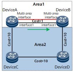
In Figure 2, the link between Device A and Device B in area 1 is a high-speed link. In area 2, traffic from Device A to Device B is forwarded along the low-speed link of Device A -> Device C -> Device D -> Device B. If you want the traffic from Device A to Device B in area 2 to be forwarded along the high-speed link of Device A -> Device B, deploy OSPF multi-area adjacency.
- An OSPF adjacency is established between Device A and Device B. For details about the establishment process, see Adjacency Establishment.
- Route calculation is implemented. For details about the calculation process, see Route Calculation.
The optimal path in area 2 obtained by OSPF through calculation is the high-speed link of Device A -> Device B. In this case, the high-speed link is shared by area 1 and area 2.