Basic VRRP Functions
VRRP works in either master/backup mode or load balancing mode.
Master/Backup Mode
A VRRP group comprises a master router and one or more backup routers. As shown in Figure 1, Device A is the master router and forwards packets, and Device B and Device C are backup routers and monitor Device A's status. If Device A fails, Device B or Device C is elected as a new master router and takes over services from Device A.
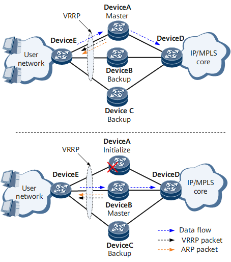
- Device A is the master. It supports delayed preemption and its VRRP priority is set to 120.
- Device B is a backup. It supports immediate preemption and its VRRP priority is set to 110.
- Device C is a backup. It supports immediate preemption and its VRRP priority is the default value 100.
VRRP in master/backup mode is implemented as follows:
When Device A functions properly, user traffic travels along the path Device E -> Device A -> Device D. Device A periodically sends VRRP Advertisement packets to notify Device B and Device C of its status.
If Device A fails, its VRRP functions are unavailable. Because Device B has a higher priority than Device C, Device B switches to the Master state and Device C remains in the Backup state. User traffic switches to the new path Device E -> Device B -> Device D.
After Device A recovers, it enters the Backup state (its priority remains 120). After receiving a VRRP Advertisement packet from Device B, the current master, Device A finds that its priority is higher than that of Device B. Therefore, Device A preempts the Master state after the preemption delay elapses, and sends VRRP Advertisement packets and gratuitous ARP packets.
After receiving a VRRP Advertisement packet from Device A, Device B finds that its priority is lower than that of Device A and changes from the Master state to the Backup state. User traffic then switches to the original path Device E -> Device A -> Device D.
Load Balancing Mode
VRRP groups work together to load-balance traffic. The implementation principles and packet negotiation mechanism of the load balancing mode are the same as those of the master/backup mode. The difference between the two modes is that in load balancing mode, two or more VRRP groups are established, and each VRRP group can contain a different master router. A VRRP device can join multiple VRRP groups and have a different priority in each group.
Multi-gateway load balancing: Multiple VRRP groups with virtual IP addresses are created and specified as gateways for different users to implement load balancing.
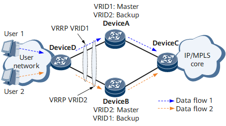
Figure 2 illustrates multi-gateway load balancing.
As shown in Figure 2, VRRP groups 1 and 2 are deployed on the network.- VRRP group 1: Device A is the master router, and Device B is the backup router.
- VRRP group 2: Device B is the master router, and Device A is the backup router.
VRRP groups 1 and 2 back up each other and serve as gateways for different users, therefore load-balancing service traffic.
Single-gateway load balancing: A load-balance redundancy group (LBRG) with a virtual IP address is created, and VRRP groups without virtual IP addresses are added to the LBRG. The LBRG is specified as a gateway to implement load balancing for all users.
Single-gateway load balancing, an enhancement to multi-gateway load balancing, simplifies user-side configurations and facilitates network maintenance and management.
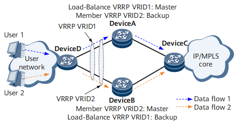
Figure 3 shows single-gateway load balancing.
As shown in Figure 3, VRRP groups 1 and 2 are deployed on the network.- VRRP group 1: an LBRG. Device A is the master router, and Device B is the backup router.
- VRRP group 2: an LBRG member group. Device B is the master router, and Device A is the backup router.
VRRP group 1 serves as a gateway for all users. After receiving an ARP request packet from a user, VRRP group 1 returns an ARP response packet and encapsulates its virtual MAC address or VRRP group 2's virtual MAC address in the response.