VPLS Description
Basic VPLS Transmission Structure
Figure 1 shows an example of a VPLS network. The entire VPLS network is similar to a switch. PWs are established over MPLS tunnels between VPN sites to transparently transmit Layer 2 packets between sites. When forwarding packets, PEs learn the source MAC addresses of these packets and create MAC entries, mapping MAC addresses to ACs and PWs.
Table 1 describes the concepts related to VPLS networks.
Name |
Full Name |
Concept |
|---|---|---|
AC |
Attachment circuit |
A link between a CE and a PE. The interface must be an Ethernet interface. |
PW |
Pseudowire |
A bidirectional virtual connection between two virtual switch instances (VSIs) residing on two PEs. A PW consists of a pair of unidirectional MPLS VCs in opposite directions. |
VSI |
Virtual switch instance |
A type of instance used to map ACs to PWs. A VSI independently provides VPLS services and forwards Layer 2 packets based on MAC addresses and VLAN tags. A VSI has the Ethernet bridge function and can terminate PWs. |
PW signaling |
PW signaling protocol |
A type of signaling used to create and maintain PWs. PW signaling is the foundation for VPLS implementation. Typically, LDP and BGP are used as the PW signaling protocols. |
Tunnel |
Tunnel |
A tunnel can carry multiple PWs. A tunnel is a direct channel that transparently transmits data between the local and remote PE devices. It can be an MPLS or a GRE tunnel. |
Forwarder |
Forwarder |
After a PE receives packets from an AC, the forwarder of the PE selects a PW to forward these packets. It is similar to a VPLS forwarding table. |
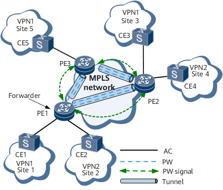
The forwarding of a packet from CE1 to CE3 on VPN1 is used as an example:
- CE1 sends a Layer 2 packet to PE1 over an AC.
- After PE1 receives the packet, the forwarder of PE1 selects a PW for forwarding the packet.
- PE1 then adds two MPLS labels to the packet based on the PW forwarding entry and tunnel information and sends the packet to PE2. The inner private label identifies the PW, and the outer public network label identifies the tunnel between PE1 and PE2.
- After PE2 receives the packet sent along the public tunnel, PE2 removes the private network label from the packet.
- The forwarder of PE2 selects an AC and forwards the packet to CE3 over the AC.
VPLS Implementation Process
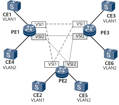
Transmission of packets between CEs relies on VSIs configured on PEs, and PWs established between the VSIs. Figure 1 shows transmission of Ethernet frames over a full mesh of PWs between PEs. Figure 2 shows transmission of Ethernet frames through a full mesh of PWs between PEs.
The Ethernet often uses the Spanning Tree Protocol (STP) to prevent loops. VPLS networks, however, use a full mesh of PWs and split horizon to avoid loops:
- PEs on a VPLS network must be fully meshed. That is, a PE must create a tree path to every other PE on the VPLS network.
- Each PE must support split horizon to prevent loops. Split horizon requires that packets received from a PW in a VSI should not be forwarded to other PWs in the VSI. Any two PEs on a VPLS network must communicate over a direct PW, which explains why a VPLS network requires a full mesh of PWs between PEs.
A PE on a VPLS network consists of a control plane and a forwarding plane.
The control plane of a VPLS PE is responsible for PW establishment, including:
- Member discovery: a process in which a PE in a VSI discovers other PEs in the same VSI. You can manually configure or use a protocol to automatically complete the configuration. The latter is called automatic discovery.
- Signaling mechanism: PWs between PEs with the same VSI ID are established, maintained, or torn down using signaling protocols, such as LDP and BGP.
The forwarding plane of a VPLS PE is responsible for data forwarding over the PW, including:
- Encapsulation: After receiving Ethernet frames from a CE, a PE encapsulates the frames into packets and sends the packets to a PSN.
- Forwarding: A PE determines how to forward a packet based on the inbound interface and destination MAC address of the packet.
- Decapsulation: After receiving packets from a PSN, a PE decapsulates these packets into Ethernet frames and sends the frames to a CE.
VPLS Encapsulation Types
Packet encapsulation types on AC interfaces
Packet encapsulation on AC interfaces depends on the user access mode, which can be VLAN or Ethernet access. The default user access mode is VLAN access.
Table 2 Packet encapsulation types on AC interfaces Packet Encapsulation Type on AC Interfaces
Description
VLAN access
Each Ethernet frame transmitted between CEs and PEs carries a VLAN tag called a Provider-tag (P-tag). This is a service delimiter identifying users on an ISP network.
Ethernet access
Ethernet frames transmitted between CEs and PEs do not necessarily carry VLAN tags. If an Ethernet frame carries a VLAN tag, the tag is an internal VLAN tag called a user-tag (U-tag) in user packets. The U-tag is carried in a packet before the packet is sent to a CE and is not added by the CE. The U-tag is used by the CE to identify to which VLAN the packet belongs and is meaningless to PEs.
Packet encapsulation on PWs
The PW ID and PW encapsulation type together uniquely identify a PW. The PW IDs and PW encapsulation types configured on both end PEs of a PW must be the same. The packet encapsulation types of packets on PWs can be raw or tagged. By default, packets on PWs are encapsulated in tagged mode.
Table 3 Packet encapsulation types Packet Encapsulation on PWs
Description
Raw
Packets transmitted over a PW cannot carry P-tags. If a PE receives a packet with the P-tag from a CE, the PE strips the P-tag and adds double labels (outer tunnel label and inner VC label) to the packet before forwarding it. If a PE receives a packet with no P-tag from a CE, the PE directly adds double labels (outer tunnel label and inner VC label) to the packet before forwarding it. The PE determines whether to add the P-tag to a packet, depending on the configuration, before sending it to a CE. The PE is not allowed to rewrite or remove an existing U-tag.
Tagged
Packets transmitted over a PW must carry P-tags. If a PE receives a packet with the P-tag from a CE, the PE directly adds double labels (outer tunnel label and inner VC label) to the packet before forwarding it. If a PE receives a packet with no P-tag from a CE, the PE adds a null P-tag and double labels (outer tunnel label and inner VC label) to the packet before forwarding it. The PE determines whether to rewrite, remove, or preserve the P-tag of a packet, depending on the configuration, before forwarding it to a CE.
In a scenario where a sub-interface is connected to an L2VPN, to ensure normal communication between a Huawei device and a non-Huawei device, you can configure the PE to change the P-tag of packets entering a PW in tagged mode.
In a scenario where a main interface accesses an L2VPN, the main interface adds an empty tag to each packet by default, adds two MPLS labels to each packet, and then forwards the packets.
Encapsulation modes of packets transmitted over ACs and PWs can be used together. The following uses Ethernet access in raw mode (without the U-tag) and VLAN access in tagged mode (with the U-tag) as examples to describe the packet exchange process.
Ethernet access in raw mode (without U-tag)
As shown in Figure 3, ACs use Ethernet encapsulation and PWs use raw encapsulation; packets transmitted from CEs to PEs do not carry U-tags.
The packet exchange process in Ethernet access in raw mode is as follows:
CE1 sends to PE1 a packet that is encapsulated at Layer 2 and does not carry any U-tag or P-tag.
After receiving the packet, PE1 searches the corresponding VSI for the entry, and selects a tunnel and a PW for the packet. PE1 adds double MPLS labels (outer tunnel label and inner VC label) to the packet based on the selected tunnel and PW, performs Layer 2 encapsulation, and forwards the packet to PE2.
PE2 receives the packet from PE1 and decapsulates the packet to remove Layer 2 encapsulation information and two MPLS labels.
PE2 sends the original Layer 2 packet to CE2.
The processing of sending a packet from CE2 to CE1 is similar to this process.
VLAN access in tagged mode (with the U-tag)
As shown in Figure 4, ACs use VLAN encapsulation and PWs use tagged encapsulation; packets transmitted from CEs to PEs carry U-tags and P-tags.
The packet exchange process in VLAN access in tagged mode (with the U-tag) is as follows:
CE1 sends to PE1 a packet that is encapsulated at Layer 2 and carries both a U-tag and a P-tag.
Upon receipt of the packet, PE1 does not process the two tags. PE1 retains the U-tag because it treats the U-tag as service data.
PE1 retains the P-tag because a packet sent to a PW with the tagged packet encapsulation mode must carry a P-tag.
PE1 queries entries in the VSI, and selects a tunnel and a PW for the packet.
PE1 adds double MPLS labels (outer tunnel label and inner VC label) to the packet based on the selected tunnel and PW, performs Layer 2 encapsulation, and forwards the packet to PE2.
PE2 receives the packet from PE1 and decapsulates the packet to remove Layer 2 encapsulation information and two MPLS labels.
PE2 sends the original Layer 2 packet that is decapsulated from CE1 to CE2. The packet contains the U-tag and the replaced P-tag.
The processing of sending a packet from CE2 to CE1 is similar to this process.


VPLS Access Modes
VLANIF interface in switching or routing mode
There are two types of VLANIF interfaces:
A VLANIF interface in routing mode is multiplexed from a physical interface. For example, a GE interface can be divided into multiple sub-interfaces, with each sub-interface acting as a VLANIF interface in routing mode.
A VLANIF interface in switching mode is a logical interface, but not the sub-interface of a physical interface. A VLANIF interface in switching mode can contain multiple physical interfaces and receive VLAN packets from these physical interfaces.
A physical interface in a VLANIF interface in switching mode can send VLAN packets in the following modes:
Access mode: allows only VLAN packets with the default VLAN ID to pass through.
Trunk mode: allows only VLAN packets with the VLAN ID of the local VLANIF interface to pass through.
CE-to-PE access mode
A CE can access a PE in the following modes:
Through an access port: An access port allows only default VLAN packets of this port to pass. The VLAN packets on this physical port are untagged.
You can assign multiple access ports of the PE to a VLAN for user access.
You can assign multiple access ports of the PE to a VLAN for user access. Through a trunk port: A trunk port allows the packets of multiple VLANs to pass. Packets of the default VLAN (one of these VLANs) are untagged, whereas packets of other VLANs are tagged. You can connect the trunk port of the PE to the Ethernet switch to allow the access of multiple VLAN users.
Derivative VPLS Functions
Traffic statistics collection
Traffic statistics can be collected based on VSIs or VSI peers, and the status of various types of traffic can be viewed in real time.
VPLS service isolation
Users of different services can be isolated using different VSIs. Users in the same VSI also need to be isolated. VPLS service isolation allows you to prevent communication between users who have the same service and are bound to the same VSI. For example, high-speed Internet (HSI) users bound to the same VSI cannot communicate with each other. For details, see section VPLS Service Isolation.