VPLS Service Isolation
Users of different services can be isolated using different VSIs. Users in the same VSI also need to be isolated.
Service Isolation Modes
VPLS networks, however, use a full mesh of PWs and split horizon to prevent loops. Split horizon means that if a packet is received along a PW of VSI, the packet is not forwarded along other PWs associated with the same VSI. VPLS supports either the hub or spoke service isolation mode. In hub mode, traffic forwarding must comply with split horizon rules. In spoke mode, traffic forwarding does not comply with split horizon rules. As described in Table 1, traffic cannot be exchanged between hub AC interfaces or between hub PWs in a VSI. ("T" indicates that traffic can be exchanged between AC interfaces or between PWs, and "F" indicates that traffic cannot be transmitted between AC interfaces or between PWs.)
Isolation of Traffic of Users Through Different VSIs
If PE resources are sufficient and the network structure is clear, you can use different VSIs to isolate traffic of different users. In this way, users are grouped and allocated to different VPLS VSIs. Users in a VSI cannot communicate with users in another VSI.
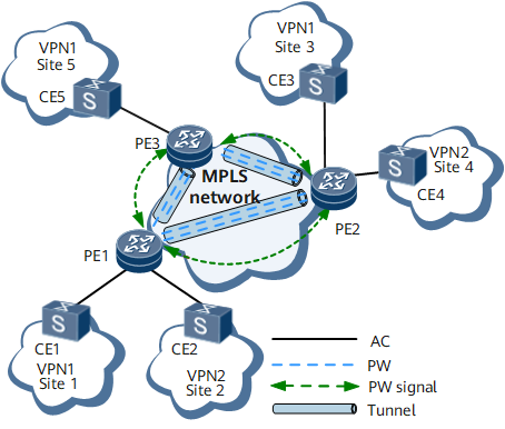
As shown in Figure 1, CE1, CE2, CE3, CE4, and CE5 use the same type of service. CE1, CE3, and CE5 need to communicate with one another; CE2 and CE4 need to communicate with each other; CE1, CE3, and CE5 do not need to communicate with CE2 and CE4. To meet the requirements, different VSIs can be configured to isolate user traffic.
This method has the following advantages:
- The logical network structure is clear, facilitating management and control.
- MAC address learning and resource usage of different VSIs are reduced.
- If a fault occurs, this feature facilitates fault locating and maintenance and reduces the fault locating access.
The disadvantage is that the modification poses a great impact if mutual access requirements are adjusted.
Isolation of Different Users of the Same Service in the Same VSI
Service isolation requirements of a VSI are classified into the following types:
- Local access users in the same VSI are isolated as needed.
- Local access users and remote access users in the same VSI are isolated.
In a common VPLS scenario, the default attribute of an AC interface is spoke, and the default attribute of a PW is hub.
In this case, a VSI is configured on PE1 and the VSI is bound to PE1's AC interface. Then, you can disable the traffic forwarding in spoke mode to prevent all local users on PE1 from communicating with each other. As shown in Table 2, services on spoke ACs are isolated from one another. The AC attribute of the VSI is changed from spoke to hub and the traffic exchange between the hub AC and hub PW is disabled. In this way, the communication between some local users on PE1 and between local access users on PE1 and remote users is isolated, implementing isolation of different users of the same service in the same VSI.
Name |
Hub AC |
Spoke AC |
Hub PW |
Spoke PW |
|---|---|---|---|---|
Hub AC |
F |
T |
T |
T |
Spoke AC |
T |
F |
T |
F |
Hub PW |
T |
T |
F |
T |
Spoke PW |
T |
F |
T |
F |
In an HVPLS scenario, the default attributes of AC interfaces and PWs between SPEs and UPEs is spoke, and the default attribute of PWs between SPEs is hub.
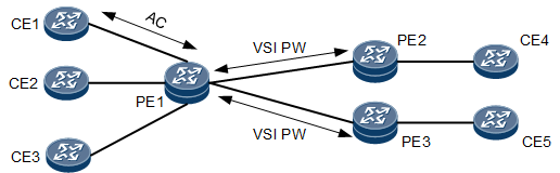
On the network shown in Figure 3, when the SPE designates the UPEs as peers, the attribute of the PWs between the SPE and the UPEs changes to spoke. In this case, all local CEs (CE1, CE2, and CE3) connected to the SPE can communicate with one another, and with the remote CE4 connected to UPE1 and remote CE5 connected to UPE2. In addition, CE4 connected to UPE1 and CE5 connected to UPE2 can communicate with each other. In this case, disabling traffic interworking in spoke mode means disabling traffic interworking between spoke ACs, between spoke ACs and UPE PWs, and between UPE PWs.
