NG MVPN Reliability
Protection Solution |
Protection Position |
Characteristics |
|---|---|---|
Sender CEs, receiver PEs, and nodes and links between sender CEs and receiver PEs |
Advantage: The network does not have redundant multicast traffic. Disadvantages:
|
|
Entire network |
Advantage: The entire network can be protected. Disadvantages:
|
|
Sender PEs (P-tunnels can also be protected after this solution is deployed) |
Advantage: The network uses BFD or flow based detection to detect link faults, implementing fast route convergence and high network reliability. Disadvantages:
|
|
MPLS tunnel protection, such as P2MP TE FRR NOTE:
For more information about P2MP TE FRR, see P2MP TE. |
P-tunnels |
Advantage: MPLS tunnel protection technologies are mature and highly reliable. Disadvantage: Only link protection is supported. |
Single-MVPN Networking Protection
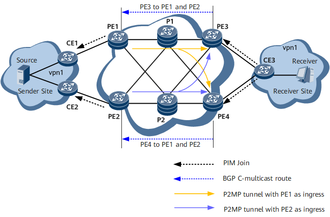
Appropriate NG MVPN networking can protect traffic transmitted over the NG MVPN without using any reliability mechanisms. Single-MVPN networking protection is such an NG MVPN protection solution. In single-MVPN networking protection, only one sender PE sends multicast traffic to receiver PEs.
Scenario in Which No Fault Occurs
- Multicast joining process: After CE3 receives a multicast group join request from a receiver, CE3 sends a PIM Join message to PE3. Upon receipt, PE3 converts the message to a BGP C-multicast route and sends the route to PE1, its BGP MVPN peer. Upon receipt, PE1 converts the route to a PIM Join message and sends the message to the multicast source. Then, the receiver joins the multicast group.
- Multicast forwarding process: After PE1 receives multicast traffic from the multicast source, PE1 sends the multicast traffic to PE3 over the P2MP tunnel. Upon receipt, PE3 sends the traffic to CE3, which in turn sends the traffic to the multicast receiver.
Scenario in Which a Fault Occurs
Table 2 lists the possible points of failure on the network shown in Figure 1 and describes the corresponding network convergence processes.
No. |
Point of Failure |
Network Convergence Process |
|---|---|---|
1 |
CE1 or link between PE1 and the multicast source |
The network can rely only on unicast route convergence for recovery. The handling process is as follows:
|
2 |
PE1 |
The network can rely only on unicast route convergence for recovery. The handling process is as follows:
|
3 |
Public network link |
If MPLS tunnel protection is configured, the network relies on MPLS tunnel protection for recovery. The MVPN is unaware of public network link changes. If MPLS tunnel protection is not configured, the network relies on unicast route convergence for recovery. In this situation, the handling process is similar to the process for handling PE1 failures. |
4 |
PE3 |
The network can rely only on unicast route convergence for recovery. The handling process is as follows:
|
In single-MVPN networking protection, if PE3 and PE4 both receive PIM Join messages but their upstream peers are different (for example, the upstream peer is PE1 for PE3 and PE2 for PE4), PE1 and PE2 both send multicast traffic to PE3 and PE4. In this situation, you need to ensure that PE3 accepts only the multicast traffic from PE1 and PE4 accepts only the multicast traffic from PE2. Specifically, you need to create multiple P2MP tunnels (with each I-PMSI tunnel corresponding to one P2MP tunnel) if a receiver PE joins multiple I-PMSI tunnels. Then, when multicast traffic reaches the receiver PE over multiple I-PMSI tunnels, the receiver PE permits the traffic received from the P2MP tunnel corresponding to the upstream neighbor according to its VPN instance multicast routing table and discards traffic received from other tunnels.
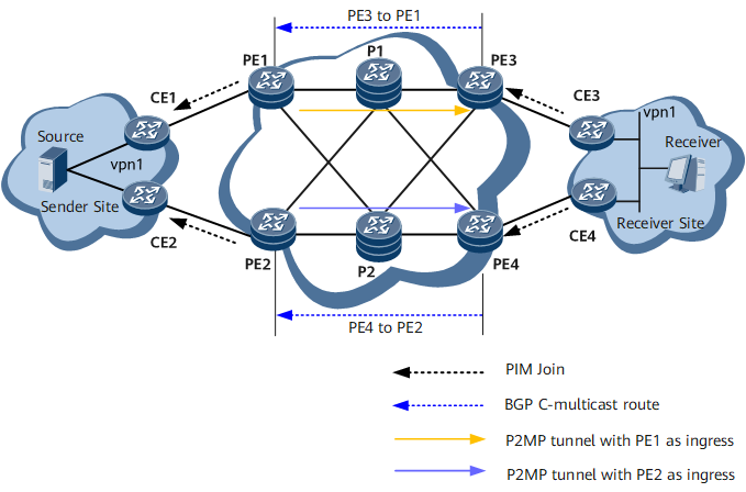
Dual-MVPN Networking Protection
- On the control plane
- The master sender and receiver PEs belong to one MVPN; the backup sender and receiver PEs belong to another MVPN.
- One receiver CE sends a PIM Join message to the master receiver PE, and the other receiver CE sends a PIM Join message to the backup receiver PE. The master receiver PE sends a BGP C-multicast route to the master sender PE, whereas the backup receiver PE sends a BGP C-multicast route to the backup sender PE.
- The master and backup sender PEs convert received BGP C-multicast routes to PIM Join messages and send these messages to the two sender CEs. The two CEs then construct two MDTs.
- On the data plane
- The master and backup sender PEs send multicast traffic received from different sender CEs to the master and backup receiver PEs respectively over different P2MP tunnels.
- The master and backup receiver PEs send received multicast traffic to corresponding receiver CEs.
- The receiver CEs send received multicast traffic to corresponding multicast receivers.
Scenario in Which No Fault Occurs
- CE3 serves as a DR. After CE3 receives a multicast group join request from a receiver, CE3 sends a PIM Join message to PE3. Upon receipt, PE3 converts the message to a BGP C-multicast route and sends the route to PE1, its BGP MVPN peer. Upon receipt, PE1 converts the BGP C-multicast route to a PIM Join message and sends the message to CE1. Upon receipt, CE1 establishes an MDT. Then, multicast traffic can be transmitted from the multicast source to the multicast receiver along the path CE1 -> PE1 -> P1 -> PE3 -> CE3.
- CE4 serves as a non-DR. After CE4 receives a multicast group join request from a receiver, CE4 does not send a PIM Join message upstream. To implement traffic redundancy, configure static IGMP joining on CE4, so that CE4 can send a PIM Join message to PE4. After PE4 receives the message, PE4 converts the message to a BGP C-multicast route and sends the route to PE2. Upon receipt, PE2 converts the route to a PIM Join message and sends the message to CE2. Upon receipt, CE2 establishes an MDT. Then, multicast traffic can be transmitted along the path CE2 -> PE2 -> P2 -> PE4 -> CE4. The multicast traffic will not be forwarded to receivers because CE4 is a non-DR.
Scenario in Which a Fault Occurs
Table 3 lists the possible points of failure on the network shown in Figure 2 and describes the corresponding network convergence processes.
No. |
Point of Failure |
Network Convergence Process |
|---|---|---|
1 |
CE1 or link between PE1 and the multicast source |
The network relies on unicast route convergence for recovery. The handling process is as follows:
|
2 |
PE1 |
The network relies on unicast route convergence for recovery. The handling process is as follows:
|
3 |
Public network link |
If MPLS tunnel protection is configured, the network relies on MPLS tunnel protection for recovery. The MVPN is unaware of public network link changes. If MPLS tunnel protection is not configured, the network relies on unicast route convergence for recovery. In this situation, the handling process is similar to the process for handling PE1 failures. |
4 |
PE3 |
The network relies on unicast route convergence for recovery. The handling process is as follows:
|
5 |
CE3 |
After CE4 uses BFD for PIM to detect that CE3 is faulty, CE4 starts to serve as a DR and adds the downstream outbound interface on the path to the multicast receiver to the corresponding multicast entry. Then, CE4 starts to send the multicast traffic received from the multicast source to the multicast receiver. |
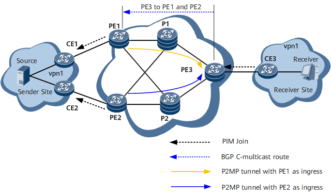
Dual-Root 1+1 Protection
In an MVPN scenario, if a sender PE on a P2MP tunnel fails, the VPN multicast service will be interrupted. The network can rely only on unicast route convergence for recovery. However, unicast route convergence is slow and may fail to meet the high reliability requirements of some multicast services. To solve the preceding problem, use BFD for P2MP TE/mLDP based or flow detection based dual-root 1+1 protection to protect public network nodes. The configuration is as follows:
Configure PE1 and PE2 as sender PEs for the MVPN. Configure RSVP-TE/mLDP P2MP on PE1 and PE2, so that two RSVP-TE/mLDP P2MP tunnels rooted at PE1 and PE2 respectively can be established. PE3 serves as a leaf node of both tunnels.
Configure PE to use BFD for P2MP TE/mLDP to detect public network node or link failures.
Configure VPN FRR on PE3, so that PE3 can have two routes to the multicast source. PE3 uses the route advertised by PE1 as the primary route and the route advertised by PE2 as the backup route.
Configure MVPN FRR on PE3 to import VPN multicast traffic to the primary and backup routes.

In a BFD for NG MVPN over P2MP scenario, if the leaf node of a P2MP tunnel is configured with a default static route, the leaf node forwards the received BFD packet according to the default route. In this case, the BFD session cannot be set up. To solve this problem, you can configure mutual import of public and private network routes so that routes from the public network are copied to the NG MVPN network. This ensures that the leaf node can forward the BFD packet received from the P2MP tunnel.
Configure PE1 and PE2 as sender PEs for the MVPN. Configure RSVP-TE/mLDP P2MP on PE1 and PE2, so that two RSVP-TE/mLDP P2MP tunnels rooted at PE1 and PE2 respectively can be established. PE3 serves as a leaf node of both tunnels.
Configure VPN FRR on PE3, so that PE3 can have two routes to the multicast source. PE3 uses the route advertised by PE1 as the primary route and the route advertised by PE2 as the backup route.
Configure MVPN FRR on PE3 and specify the flow based detection as the detection method of MVPN FRR.
Scenario in Which No Fault Occurs
- Multicast joining process: After CE3 receives a multicast group join request from a receiver, CE3 sends a PIM Join message to PE3. Upon receipt, PE3 converts the message to a BGP C-multicast route and sends the route to PE1 and PE2, its BGP MVPN peers. Upon receipt, PE1 and PE2 convert the route to a PIM Join message and send the message to the multicast source. Then, the multicast receiver joins the multicast group.
- Multicast forwarding process: After PE1 receives multicast traffic from the multicast source, PE1 sends the multicast traffic to PE3 over the RSVP-TE/mLDP P2MP tunnel. Upon receipt, PE3 sends the traffic to CE3, which in turn sends the traffic to the multicast receiver. After PE3 receives the multicast traffic sent over the RSVP-TE/mLDP P2MP tunnel rooted at PE2, PE3 drops the traffic.
Scenario in Which a Fault Occurs
- BFD for P2MP TE/mLDP based dual-root 1+1 protection
Table 4 shows the possible points of failure on the network shown in Figure 3 and the network convergence processes.
Table 4 Possible points of failure and network convergence processes No.
Point of Failure
Network Convergence Process
1
PE1 or the P2MP tunnel connected to PE1
If a fault occurs on the RSVP-TE/mLDP P2MP tunnel, PE3 can use BFD for P2MP TE/mLDP to quickly detect the fault and choose to accept the multicast traffic sent by PE2. Traffic switchover can be completed within 50 ms. The specific route convergence time depends on the fault detection time of BFD for P2MP TE/mLDP.
The disadvantage of dual-root 1+1 protection is that redundant traffic exists on the public network.
2
P1 or the link connected to P1
The handling process is similar to the process for handling PE1 or the P2MP tunnel connected to PE1 failures.
3
Public network tunnel
If MPLS tunnel protection is configured, the network relies on MPLS tunnel protection for recovery. If MPLS tunnel protection is not configured, the network relies on dual-root 1+1 protection for recovery.
- Flow detection based dual-root 1+1 protection
Table 5 shows the possible points of failure on the network shown in Figure 3 and the network convergence processes.
Table 5 Possible points of failure and network convergence processes No.
Point of Failure
Network Convergence Process
1
PE1 or the P2MP tunnel connected to PE1
If a fault occurs on the nodes or tunnel of primary link, PE3 can use flow-based detection to quickly detect the fault and choose to accept the multicast traffic received from backup link.
2
P1 or the link connected to P1
The handling process is similar to the process for handling PE1 or the P2MP tunnel connected to PE1 failures.
3
Public network tunnel
The handling process is similar to the process for handling PE1 or the P2MP tunnel connected to PE1 failures.