PW APS

This chapter applies only to the NetEngine 8000 F1A.
Definition
Two PW reliability mechanisms are currently available: PW redundancy and PW automatic protection switching (APS).
APS instructs the source and destination ends to implement protection switching in the same manner to achieve traffic switching, delayed switching, and wait-to-restore. APS protocol packets are always transmitted along the backup channel. Both the transmit and receive ends know that they receive APS protocol packets through each other's backup channel. This implementation helps determine whether both ends are configured with the same primary and backup channels.
PW APS is an application of APS on PWs. PW APS uses PW OAM to monitor the PW status. If a PE detects that the primary PW fails, PW APS is triggered, and traffic is switched to the secondary PW, implementing service protection.
Purpose
- Static solution: uses static routes, static LSPs, and static PWs.
- Dynamic solution: uses dynamic routes, dynamic LSPs/TE tunnels, and dynamic PWs.
- PW APS uses PW OAM (MPLS OAM or MPLS-TP OAM) to rapidly monitor PW status and notifies APS of the status.
The primary and secondary PWs must use OAM of the same type. To configure OAM for a bypass PW, it must also use the same type of OAM as the primary and secondary PWs.
- The primary/secondary PW protection group is associated with APS instances. APS instructs the source and destination ends to implement bidirectional PW protection switching in the same manner, as defined in G.8131.
PW APS applies to SVC, LDP, or PWE3 PWs.
Using PW APS or PW redundancy solely on the entire network is recommended. PW APS and PW redundancy are both reliability mechanisms but are implemented differently. Implementing both mechanisms on a network increases the difficulties for network maintenance.
Basic Concepts
Protection Type
PW APS can work in 1:1 or 1+1 mode, in which primary and secondary PWs back up each other. In PW APS 1:1 mode, traffic is transmitted and received over a single link. In PW APS 1+1 mode, traffic is transmitted and received over double links but accepted over only one link.
Switching Type
Dual-ended switching
Dual-ended switching refers to bidirectional switching, that is, if a fault is detected on the forward or reverse working PW, APS allows bidirectional services on the working PW to be switched to the protection PW.
Single-ended switching
Single-ended switching refers to unidirectional switching, that is, if a fault is detected on the forward or reverse working PW, the service only in the fault direction of the working PW is switched to the protection PW. Single-end switching is also called pseudo wire fast protection switching (PW FPS).
Revertive Mode
The PW APS mode can be either revertive or non-revertive. In non-revertive mode, traffic will not be switched back from the protection PW to the working PW even if the working PW recovers. In revertive mode, traffic will return to the working PW after the wait-to-restore (WTR) timer configured for the working PW expires.
WTR Time
The WTR time is counted from the time when the primary PW recovers to the time when traffic is switched back from the secondary PW. Setting a WTR time prevents frequent traffic switching.
Delayed Switching Time
The delayed switching time is the time after which a protection switching is triggered if a signal fail (SF) is still detected on a PW. Setting a delayed switching timer prevents switching from immediately occurring after an SF is detected.
Dual-Homing Protection
Dual-homing protection is implemented by connecting two PEs to a CE through respective ACs. This protects PE services on the bearer network.
PW APS Bundling
The device usually needs to undergo a great deal of PW APS protection switching. If PW APS enables a state machine for each protection switching, the device will not be able to implement all protection switching due to limited resources and capabilities. Configuring an APS state machine to process a great deal of PW APS protection switching decreases resource consumption. This APS state machine is shared by multiple PWs, which is called PW APS bundling.
Switching Mechanism
PW APS uses PW OAM to monitor the primary and secondary PW status. PW OAM sends detection packets from the ingress to the egress periodically. If the egress fails to receive any detection packets in a certain period, it considers that an SF occurs and notifies the remote APS module of the fault. This implements service switching and protection.
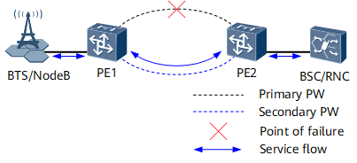
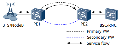
As shown in Figure 1, PW APS is configured on PE1 and PE2. Normally, upstream traffic from a BTS/NodeB is transmitted along the path PE1 -> primary PW -> PE2 on the PSN. PE2 forwards the traffic to a BSC/RNC. Downstream traffic from a BSC/RNC is transmitted along the path PE2 -> primary PW -> PE1 on the PSN. PE1 forwards the traffic to a BTS/NodeB.
As shown in Figure 2, if the primary PW fails, PW OAM on PE1 and PE2 detects the failure and triggers APS. Both upstream and downstream traffic are switched to the secondary PW.
The delayed revertive operation mode is used for PW APS by default. After the primary PW recovers, PW OAM on PE1 and PE2 detects the recovery but waits a delayed switching time before triggering an APS revertive operation. Both upstream and downstream traffic are then switched back to the primary PW.