L2TPv3 Fundamentals
L2TPv3 Tunnel
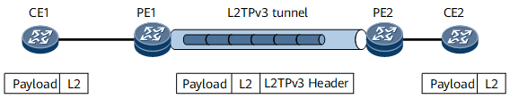
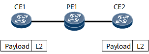
Access to an L2TPv3 tunnel in whole-interface mode
On the network shown in Figure 1, an L2TPv3 tunnel is established between PE1 and PE2. An EVC sub-interface with the default encapsulation mode serves as the L2TPv3 interface on each PE. CE1 and CE2 can exchange either tagged or untagged packets over the L2TPv3 tunnel:
- Processing on the inbound interface: Traffic from CE1 accesses PE1 through PE1's EVC sub-interface.
- Processing on the outbound interface: Traffic from PE2 arrives at CE2 through PE2's EVC sub-interface.
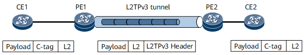
Access to an L2TPv3 tunnel in C-tag termination mode
On the network shown in Figure 2, an L2TPv3 tunnel is established between PE1 and PE2. An EVC sub-interface with the default encapsulation mode serves as the L2TPv3 interface on each PE. CE1 and CE2 can exchange packets carrying only C-tags:
Processing on the inbound interface: Traffic from CE1 accesses PE1 through PE1's EVC sub-interface. The EVC sub-interface is configured to match user packets carrying only C-tags and strip the C-tags of these packets before forwarding these packets to the L2TPv3 tunnel.
Processing on the outbound interface: Traffic from PE2 arrives at CE2 through PE2's EVC sub-interface. The EVC sub-interface is configured to add a C-tag to each user packet before forwarding these packets to CE2.
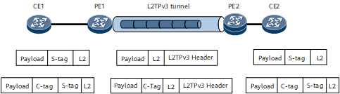
- Access to an L2TPv3 tunnel in S-tag termination mode
On the network shown in Figure 3, an L2TPv3 tunnel is established between PE1 and PE2. An EVC sub-interface with the default encapsulation mode serves as the L2TPv3 interface on each PE. CE1 and CE2 can exchange packets carrying S-tags, no matter whether these packets also carry C-tags:
Processing on the inbound interface: Traffic from CE1 accesses PE1 through PE1's EVC sub-interface. The EVC sub-interface is configured to match user packets carrying S-tags and strip the S-tags before forwarding these packets to the L2TPv3 tunnel.
Processing on the outbound interface: Traffic from PE2 arrives at CE2 through PE2's EVC sub-interface. The EVC sub-interface is configured to add an S-tag to each user packet before forwarding these packets to CE2.
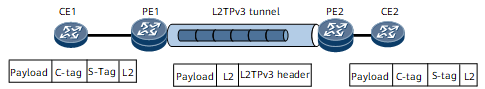
Access to an L2TPv3 tunnel in S-tag+C-tag termination mode
On the network shown in Figure 4, an L2TPv3 tunnel is established between PE1 and PE2. An EVC sub-interface with the default encapsulation mode serves as the L2TPv3 interface on each PE. CE1 and CE2 can exchange packets carrying both C-tags and S-tags:
Processing on the inbound interface: Traffic from CE1 accesses PE1 through PE1's EVC sub-interface. The EVC sub-interface is configured to match user packets carrying both C-tags and S-tags and strip these tags before forwarding these packets to the L2TPv3 tunnel.
Processing on the outbound interface: Traffic from PE2 arrives at CE2 through PE2's EVC sub-interface. The EVC sub-interface is configured to add a C-tag and an S-tag to each user packet before forwarding these packets to CE2.
L2TPv3 Local Switching Connection
On the network shown in Figure 5, CE1 and CE2 exchange packets through PE1. Two EVC sub-interfaces with the default encapsulation mode serve as L2TPv3 interfaces on PE1. PE1, which only transparently transmits service packets, allows service packets to use any encapsulation type:
- Processing on the inbound interface: Traffic from CE1 accesses PE1 through PE1's EVC sub-interface.
- Processing on the outbound interface: Traffic from PE1 arrives at CE2 through PE1's another EVC sub-interface.
Traffic Injection by an L2TPv3 Tunnel for Another L2TPv3 Tunnel
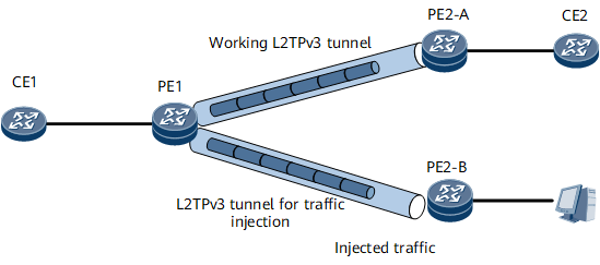
On the network shown in Figure 6, an L2TPv3 tunnel is established between PE1 and PE2-A and between PE1 and PE2-B. CE1 and CE2 exchange packets over the L2TPv3 tunnel between PE1 and PE2-A. The L2TPv3 tunnel between PE1 and PE2-B is used to inject traffic. After PE1 receives injected packets from PE2-B, PE1 strips the L2TPv3 headers of these packets and determines whether the destination MAC addresses of these packets are the same as the MAC address of its AC interface connecting to CE1. If the destination MAC addresses of these packets are the same as the MAC address of the AC interface, PE1 sends these packets to CE1. Otherwise, PE1 sends these packets to CE2 over the L2TPv3 tunnel between itself and PE2-A to test traffic forwarding.
Traffic Injection by an L2TPv3 Tunnel for an IPv4/IPv6 link
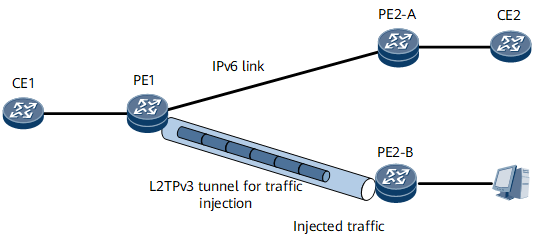
On the network shown in Figure 7, an IPv4/IPv6 link is established between PE1 and PE2-A for IPv4/IPv6 traffic forwarding and an L2TPv3 tunnel is established between PE1 and PE2-B to inject traffic. After packets from CE1 arrive at PE1, PE1 forwards these packets over the IPv4/IPv6 link. After PE1 receives injected packets from PE2-B, PE1 strips the L2TPv3 headers of these packets and determines whether the destination MAC addresses of these packets are the same as the MAC address of its AC interface connecting to CE1. If the destination MAC addresses of these packets are the same as the MAC address of the AC interface, PE1 sends these packets to CE1. Otherwise, PE1 sends these packets to PE2-A over the IPv4/IPv6 link between itself and PE2-A to test traffic forwarding.