BGP A-D MVPN
Background
- PIM-SM MDT: an MDT established by sending PIM-SM Join messages to the intermediate device RP. PIM-SM MDTs are used in scenarios in which the location of the multicast source (MTI) is unknown.
- PIM-SSM MDT: an MDT established by sending PIM-SSM Join messages to the multicast source. PIM-SSM MDTs are used in scenarios in which the location of the multicast source (MTI) is known.
A PIM-SSM MDT can be established only when the location of the public network multicast source (address of the MTI on the PE) is known.
In MD MVPN scenarios, however, a PE cannot obtain the MTI address of the peer PE before an MDT is established. Therefore, only the PIM-SM MDT can be used in this case. You can configure the RP on the public network and establish a public network MDT for PEs through the RP.
In BGP A-D MVPN scenarios, MDT-AD routes are transmitted through BGP MDT-AD messages. MDT-AD routes carry the public multicast source address, and a PE can obtain the MTI address of the peer PE. Therefore, a PIM-SSM MDT can be established in this case to transmit multicast protocol and data packets.
In both the MD MVPN and BGP A-D MVPN scenarios, all PEs are logically fully-meshed, and public network MDTs must be established between PEs. Therefore, public network MDTs can be established, regardless of whether there is VPN traffic.
The establishment of public network MDTs is related only to the configurations of the VPN Share-Group address and Mtunnel interface.
Related Concepts
MD MVPN: See MVPN Terms.
Peer: a BGP speaker that exchanges messages with another BGP speaker.
BGP A-D: a mechanism in which PEs exchange BGP Update packets that carry A-D route information to obtain and record peer information of a VPN.
Implementation
For multicast VPN in BGP A-D mode, only MDT-SAFI A-D is supported, in which a new address family is defined by BGP. In this manner, after a VPN instance is configured on a PE, the PE advertises the VPN configuration including the RD, Share-Group address, and IP address of the MTI to all its BGP peers. After a remote PE receives an MDT-SAFI message advertised by BGP, the remote PE compares the Share-Group address in the message with its Share-Group address. If the remote PE confirms that it is in the same VPN as the sender of the MDT-SAFI message, the remote PE establishes the PIM-SSM MDT on the public network to transmit multicast VPN services.
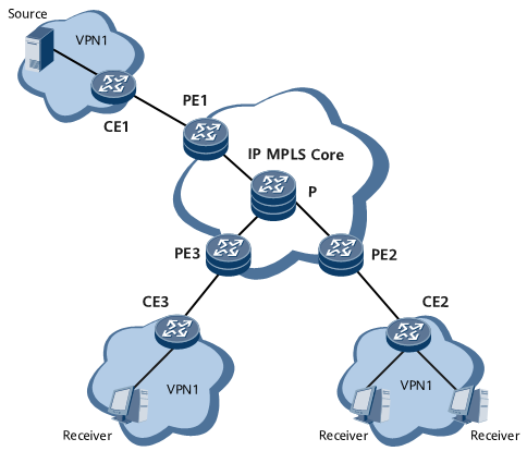
As shown in Figure 1, PE1, PE2, and PE3 belong to VPN1, and join the Share-Group G1. The address of G1 is within the SSM group address range. BGP MDT-SAFI A-D mode is enabled on each PE. In addition, the BGP A-D function is enabled on VPN1. The site where CE1 resides is connected to Source of VPN1, and CE2 and CE3 are connected to VPN1 users. Based on the BGP A-D mechanism, every PE on the network obtains and records information about all its BGP peers on the same VPN, and then directly establishes a PIM-SSM MDT on the public network for transmitting multicast VPN services. In this manner, MVPN services can be transmitted over a public network tunnel based on the PIM-SSM MDT.
After being configured with the BGP A-D function, PE1, PE2, and PE3 negotiate session parameters, and confirm that they all support the BGP A-D function. Then, the PEs can establish BGP peer relationships. After receiving a BGP Update message from PE1 and PE2, PE3 obtains and records the BGP peer addresses of PE1 and PE2. The BGP Update messages carry the information about the PEs that send the messages.
VPN1 is configured on PE3. PE3 joins the Share-Group G1. PE3 creates a PIM-SSM entry with G1 being the group address and the address of PE1 being the source address and another PIM-SSM entry with G1 being the group address and the address of PE2 being the source address. PE3 then directly sends PIM Join messages to PE1 and PE2 to establish two PIM-SSM MDTs to PE1 and PE2, respectively.
CE3 sends a Join message to PE3. After receiving the Join message, PE3 encapsulates the Join message with the PIM-SSM Share-Group address, and then sends the message to PE1 over the public network tunnel. PE1 then decapsulates the received Join message, and then sends it to the multicast source.
After the multicast data sent by the multicast source reaches PE1, PE1 encapsulates the multicast data with the Share-Group address, and then forwards it to PE3 over the public network tunnel. PE3 then forwards the multicast data to CE3, and CE3 sends the multicast data to the user.