Hop-by-hop Performance Measurement Scenarios
In end-to-end performance measurement, only the traffic entering and leaving the network is measured. This measurement reflects only the quality of the entire network. If a network fault occurs, end-to-end performance measurement cannot help locate the fault. To locate the fault, IP FPM provides hop-by-hop performance measurement. The statistics objects in hop-by-hop performance measurement scenarios are the same as that in end-to-end performance measurement scenarios.
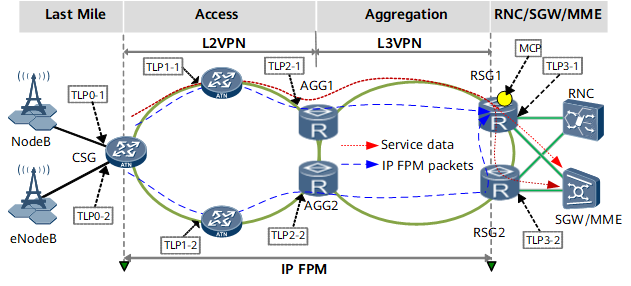
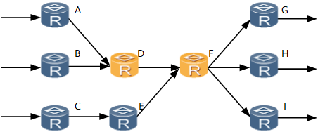
The NMS provides visualized service paths for target flows by segmenting the service forwarding path into multiple closed hops and delivering these closed hops to the DCPs and MCP.
The DCPs report the hop-by-hop measurement data to the MCP.
The MCP calculates the packet loss and delay performance for each hop.
The NMS displays the real-time data of each hop using the MIB, helping locate the fault.
Figure 1 lists how to deploy IP FPM on the network shown in Figure 1.
Deployment Object |
IP FPM Deployment |
|---|---|
TLP deployment |
Hop-by-hop performance measurement applies only to unidirectional target flows. Deploy TLPs as shown in Figure 1 for upstream traffic. Hop-by-hop performance measurement differs from end-to-end performance measurement in the following aspects:
|
DCP deployment |
Configure all devices that have TLPs deployed as DCPs to send measurement data to the MCP. |
MCP deployment |
If routes are reachable between the access and aggregation networks, deploy the MCP on an RSG. If routes are unreachable between the access and aggregation networks, deploy the MCP on an AGG. On the network in Figure 1, deploy the MCP on RSG1. |
Clock deployment |
Configure the network time protocol (NTP) or 1588v2 so that all device clocks can be synchronized. |
ACH Division Based on Measurement Sections
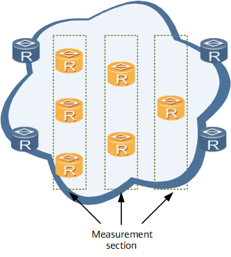
In hop-by-hop performance measurement, the MCP measures the packet loss and delay based on ACHs. The smaller scale an ACH covers, the more accuracy for fault locating. ACH division helps identify a local area, a direct link, or inbound and outbound interfaces on a device.