End-to-End Performance Measurement Scenarios
IP datacom networks, as the mainstream of datacom networks, are large in scale and provide various access modes. To maximize carriers' return on investment, reduce network construction costs, and evolve the existing network smoothly into a Long Term Evolution (LTE) network, an IP RAN solution is introduced.
IP RANs require performance measurement for SLA compliance and routine O&M performance management. As the bearer network quality (delay, jitter, and packet loss) affects the radio service quality, the bearer network department must provide optimal methods to detect the network operating status. In addition, if the service quality deteriorates, the bearer network must be able to provide its own performance data to help fault locating.
IP RAN provides a variety of solutions. The following section describes the application of IP FPM end-to-end performance measurement in HVPN, and L2+L3 mixed VPN scenarios. The service type can be the 3G Ethernet service (signaling, voice, and data), S1 service (signaling, voice, and data), OM service, or IP clock service. The service flow is identified by the source IP address, destination IP address, and DSCP value.
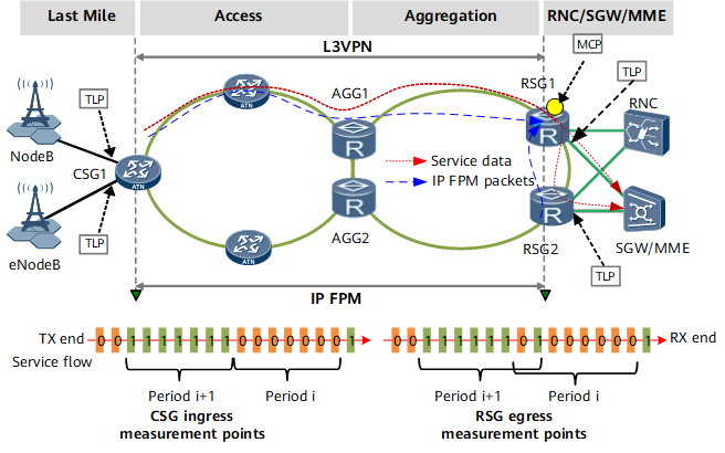
HVPN Scenarios
Figure 1 shows an HVPN networking. Table 1 lists how to deploy IP FPM in an HVPN scenario.
Deployment Object |
IP FPM Deployment |
|---|---|
TLP deployment |
Performance measurement can be implemented for E2E services
and local switching services on IP RANs. On the network shown in Figure 1:
|
DCP deployment |
Configure the CSG, RSG1, and RSG2 as DCPs to send measurement data to the MCP. |
MCP deployment |
|
Clock deployment |
Configure the network time protocol (NTP) or 1588v2 so that all device clocks can be synchronized.
|
In E2E VPN and native IP+L3VPN scenarios, deploy IP FPM in the same manner as that in HVPN scenarios.
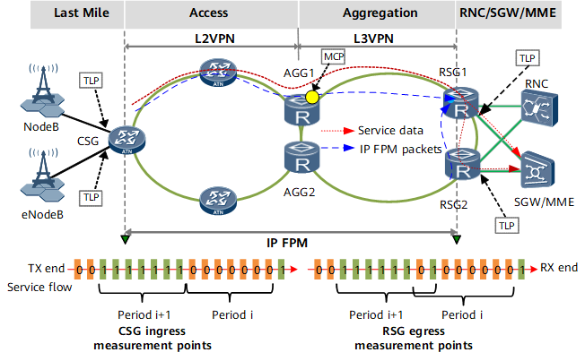
L2+L3 Mixed VPN Scenarios
Figure 2 shows an L2+L3 mixed VPN networking. Table 2 lists how to deploy IP FPM in an L2+L3 mixed VPN scenario.
Deployment Object |
IP FPM Deployment |
|---|---|
TLP deployment |
For E2E services, deploy TLPs on the AC interfaces that carry services (Layer 2 user interfaces on the CSG and Layer 2/Layer 3 user interfaces on RSGs). Configure flow characteristics based on the 5-tuple, start measurement and counting, and send measurement data to the MCP through protocol packets |
DCP deployment |
Configure the CSG, RSG1, and RSG2 as DCPs to send measurement data to the MCP. |
MCP deployment |
Routes are unreachable between the access and aggregation networks, and the CSG does not have routes to RSGs. Therefore, deploy the MCP on an AGG. On the network in Figure 2, deploy the MCP on AGG1. |
Clock deployment |
Same as that in an HVPN scenario |
ARP request messages are generated on AGGs in the downstream direction.
Broadcast traffic is generated in the downstream direction if the VSI has not learned MAC addresses.
Summary
- Supports E2E performance measurement on large-scale networks.
- Supports service-based packet loss and delay measurement with high precision.
- Applies to various networking scenarios.