PWE3 Trace Test
After being widely used, PWE3 also needs to provide O&M capabilities. PWE3 tracert, a network maintenance tool, is developed in this context.
Just like PWs are classified as SS-PWs or MS-PWs, PWE3 tracert is classified as PWE3 single-segment tracert or PWE3 multi-segment tracert.
PWE3 single-segment tracert
On the PWE3 network shown in Figure 1, CE1 and CE4 belong to VPN1; CE2 and CE3 belong to VPN2. The path is PE1 -> P -> PE4 for the LSP from PE1 to PE4 and PE2 -> P -> PE3 for the LSP from PE2 to PE3.
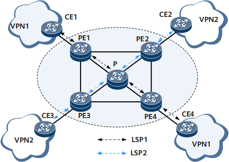
On PE1, you can start PWE3 tracert of VPN1 by using related commands. PWE3 tracert in this case is the same as LSP tracert on the public network, except that a PW label is added to packets and the local PE checks whether the PW label and VC ID carried in packets received from the remote end are the same as those on the local end.
The source PE of PWE3 tracert sends MPLS Echo Request packets with TTL in the outer label from 1 on and TTL in the inner label as 1. Upon receipt of a packet with TTL in the outer label as 1, an LSR does not forward the packet. Instead, after confirming that the service and label information carried in the packet is correct, the LSR sends an MPLS Echo Reply packet to the source PE. In this manner, the source PE collects information about each LSR and the egress PE along the LSP. Currently, MPLS Echo Reply packets are IP packets that do not carry any label.
The following uses the LSP between PE1 and PE4 as an example to explain how PWE3 tracert collects node information.
By initiating PWE3 tracert, PE1 collects information about nodes along the LSP between PE1 and PE4. By comparing paths obtained through PWE3 tracert, you can determine whether an error exists.
If PE1 collects only information about PE4 with TTL being 2 rather than information about the P with TTL being 1, PE1 regards that the P does not support MPLS ping.
If PE1 collects only information about the P with TTL being 1 rather than information about PE4 with TTL being 2, PE1 regards that PE4 or the link between the P and PE4 is faulty.
If PE1 collects information about PE1, PE2, and PE4, the P may be faulty. A new path has been generated by the protocol.
PWE3 multi-segment tracert
On the network shown in Figure 2, a multi-segment PW is established between CE1 and CE2, and the IDs of PW segments are different. The LSP path is UPE1-P1-SPE1-SPE2-P2-UPE2.
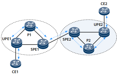
PWE3 tracert started on UPE1 can obtain a correct response only from P1 and SPE1. SPE2 and UPE2 find that the Remote PE Address and VC ID are inconsistent. This means that PWE3 tracert passes through an MS-PW. PW label switching information can be found in the downstream mapping information sent by each device.
SPE1 can start either PWE3 tracert to UPE1 or PWE3 tracert to SPE2 and UPE2. The PWE3 tracert to UPE1 can be regarded as PWE3 single-segment tracert, and the PWE3 tracert to SPE2 and UPE2 can be regarded as PWE3 multi-segment tracert.
The case with PWE3 tracert on other PEs is similar.