VPLS E-Tree
Definition
VPLS Ethernet Tree (E-Tree) is a Layer 2 Ethernet service in which root nodes can communicate with each other or with leaf nodes, but leaf nodes cannot communicate with each other.
Background
In a VPLS domain, AC interfaces bound to the same VSI can communicate with one another. It is necessary to enhance user data security and minimize mutual influence between users by controlling communication between AC interfaces.
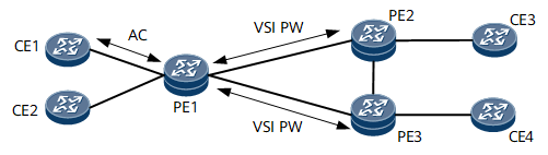
On the VPLS network shown in Figure 1, traffic needs to be isolated between CE1 and CE2, and between CE3 and CE4. Currently, only the hub and spoke mode is supported. In this mode, traffic can be isolated only on local AC interfaces (for example, traffic between CE1 and CE2 in Figure 1) or on all local and remote CEs (for example, traffic between CE1, CE2, and CE3 in Figure 1), but traffic between some local and remote CEs cannot be isolated (for example, CE1 and CE3 in Figure 1 communicate, and CE2 and CE3 are isolated from each other).
VPLS E-Tree provides a solution to inter-device AC interface isolation. VPLS E-Tree classifies AC interfaces into the following types:
Root AC interface: can communicate with leaf AC interfaces and other root AC interfaces.
Leaf AC interface: can communicate only with root AC interfaces.
Implementation
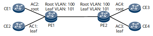
In VPLS E-Tree, an AC interface is either a root or leaf AC interface, and each VSI is assigned root and leaf VLAN IDs. A packet is attached with a VLAN tag carrying a root VLAN ID if it is from a root AC interface, or attached with a VLAN tag carrying a leaf VLAN ID if it is from a leaf AC interface. After a PE receives the packet, the PE determines whether the packet is from a leaf or root AC interface based on the VLAN tag carried in the packet:
If the packet is from a root AC interface, the PE sends the packet to all its root and leaf AC interfaces.
If the packet is from a leaf AC interface, the PE sends the packet only to all its root AC interfaces.

To implement inter-device AC interface isolation, the VSIs in a VPLS domain must use the same root VLAN IDs and same leaf VLAN IDs.
PWs can work in either of the following modes:
- Compatible mode: If PE2 does not support E-Tree, the PW of PE1 works in compatible mode. Packets sent to PE2 do not carry an E-Tree VLAN ID.
- Optimization mode: If PE2 has only leaf nodes configured, PE1 does not send packets received from the local leaf node to PE2.