BIER S-PMSI Tunnel Establishment
S-PMSI Tunnel Establishment
On an NG MVPN, multicast data traffic is transmitted through an I-PMSI tunnel to multicast users. The I-PMSI tunnel connects to all PEs on the MVPN and transmits multicast data to these PEs regardless of whether these PEs have receivers. If some PEs do not have receivers, this implementation causes traffic redundancy, wastes bandwidth resources, and increases PEs' burdens.
To solve this problem, use Selective-PMSI (S-PMSI) tunnels. An S-PMSI tunnel connects to the sender and receiver PEs of specific multicast sources and groups on an MVPN. Compared with the I-PMSI tunnel, an S-PMSI tunnel sends multicast data only to PEs interested in the data, reducing bandwidth consumption and PEs' burdens.
In the NG MVPN over BIER scenario, if the forwarding rate of multicast traffic is consistently higher than the threshold, the traffic is switched from the I-PMSI tunnel to the S-PMSI tunnel. If the forwarding rate of the multicast traffic is consistently lower than the threshold after the switchover, the traffic is switched back to the I-PMSI tunnel. Figure 1 shows the time sequence for the sender PE to initiate a switchover from the I-PMSI tunnel to the S-PMSI tunnel after the multicast traffic rate exceeds the threshold.

Step |
Device Name |
Key Action |
|---|---|---|
|
PE1 |
When PE1 detects that the multicast traffic forwarding rate is higher than the threshold, PE1 initiates a switchover from the I-PMSI tunnel to the S-PMSI tunnel and advertises a BGP S-PMSI A-D route to its BGP peers. In the BGP S-PMSI A-D route, the Leaf Information Require flag is set to 1, instructing the BGP peers that receive this route to reply with a BGP Leaf A-D route if they want to join the S-PMSI tunnel to be established. Although the control plane initiates the tunnel switchover instruction, multicast traffic is not switched to the S-PMSI tunnel until the delay timer expires. |
|
PE2 |
After receiving the BGP S-PMSI A-D route from PE1, PE2 replies with a BGP Leaf A-D route carrying the PMSI Tunnel attribute as PE2 has a receiver downstream. |
|
PE3 |
After receiving the BGP S-PMSI A-D route from PE1, PE3 does not reply with a BGP Leaf A-D route as PE3 has no receivers downstream, but PE3 records the BGP S-PMSI A-D route. PE3 does not join the S-PMSI tunnel whose information is carried in the S-PMSI A-D route. |
|
PE1 |
Upon receipt of the BGP Leaf A-D route from PE2, PE1 generates a new BitString with itself as the root node and PE2 as a leaf node. Then an S-PMSI tunnel is established. |


After PE3 has downstream receivers, PE3 will send a BGP Leaf A-D route to PE1. After receiving the route, PE1 updates the leaf node set and generates a new BIER BitString. Then a new S-PMSI tunnel is established.
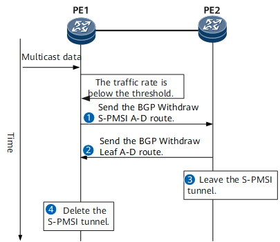
Switchback from an S-PMSI Tunnel to the I-PMSI Tunnel
If the forwarding rate of multicast traffic is lower than the threshold after the switchover, PE1 starts a hold timer for the switchback from the S-PMSI Tunnel to the I-PMSI tunnel. Table 2 describes the detailed switchback procedure.
Step |
Device Name |
Key Action |
|---|---|---|
|
PE1 |
After PE1 detects that the multicast data forwarding rate is lower than the threshold after the switchover, PE1 starts a switchback hold timer: Before the timer expires:
|
|
PE2 |
After receiving the BGP Withdraw S-PMSI A-D route from PE1, PE2 replies with a BGP Withdraw Leaf A-D route. |
|
PE2 |
After PE2 detects that none of its multicast entries is bound to the S-PMSI tunnel, PE2 leaves the S-PMSI tunnel. |
|
PE1 |
PE1 deletes the S-PMSI tunnel after waiting for a specified period of time. |


